odrivetool
The odrivetool is the accompanying PC program for the ODrive. It’s main purpose is to provide an interactive shell to control the device manually, as well as some supporting functions like firmware update.
Installation
Refer to the Getting Started guide.
Type odrivetool --help to see what features are available.
Multiple ODrives
By default, odrivetool will connect to any ODrive it finds.
If this is not what you want, you can select a specific ODrive.
To find the serial number of your ODrive, run odrivetool, connect exactly one ODrive and power it up.
You should see this:
Connected to ODrive 306A396A3235 as odrv0
In [1]:
306A396A3235 is the serial number of this particular ODrive.
If you want odrivetool to ignore all other devices you would close it and then run:
odrivetool --serial-number 306A396A3235
My ODrive is stuck in DFU mode, can I still find the serial number?
Yes, the serial number is part of the USB descriptors. In Linux you can find it by running:
(sudo lsusb -d 1209:0d32 -v; sudo lsusb -d 0483:df11 -v) 2>/dev/null | grep iSerial
This should output something like:
iSerial                 3 385F324D3037
iSerial                 3 306A396A3235
Here, two ODrives are connected.
Configuration Backup
You can use odrivetool to back up and restore device configurations or transfer the configuration of one ODrive to another one.
To save the configuration to a file on the PC, run
odrivetool backup-config my_config.jsonTo restore the configuration form such a file, run
odrivetool restore-config my_config.json
Note
The encoder offset calibration is not restored because this would be dangerous if you transfer the calibration values of one axis to another axis.
Device Firmware Update
Attention
DFU is not supported on ODrive v3.4 or earlier. You need to flash with the external programmer instead.
To update the ODrive to the newest firmware release, simply open up a terminal and run the following command:
odrivetool dfu
You should then see
ODrive control utility v0.3.7.dev
Waiting for ODrive...
Found ODrive 308039673235 (v3.5-24V) with firmware v0.3.7-dev
Checking online for newest firmware... found v0.3.7
Downloading firmware...
Putting device 308039673235 into DFU mode...
Erasing... done
Flashing... done
Verifying... done
Note
This command will connect to GitHub servers to retrieve the latest firmware.
If you have a non-default configuration saved on the device, odrivetool will try to carry over the configuration across the firmware update.
If any of the settings are removed or renamed, you will get warning messages.
Flashing Custom Firmware
If you want to flash a specific firmware file instead of automatically downloading one, you can run
odrivetool dfu path/to/firmware/file.hex
You can download one of the officially released firmware files from here.
.. You will need one of the .hex files (not the .elf`file).
On Windows you will need one of the :code:.hex` files, and for Linux and Mac you will want the .elf file.
Make sure you select the file that matches your board version.
To compile firmware from source, refer to the developer guide.
Troubleshooting
During the update, a new device called “STM32 BOOTLOADER” will appear. Open the Zadig utility and set the driver for “STM32 BOOTLOADER” to libusb-win32. After that the firmware update will continue.
Try running sudo odrivetool dfu instead of odrivetool dfu.
On some machines you will need to unplug and plug back in the USB cable to make the PC understand that we switched from regular mode to bootloader mode.
Forcing DFU Mode
If the DFU script can’t find the device, try forcing it into DFU mode:
Flick the DIP switch that says “DFU, RUN” to “DFU” and power cycle the board. If that alone doesn’t work, also connect the pin “GPIO6” to “GND”. After you’re done upgrading firmware, don’t forget to put the switch back into the “RUN” position and power cycle the board again.
Connect the pin “BOOT0” to “3.3V” and power cycle the board. If that alone doesn’t work, also connect the pin “GPIO1” to “GND”. After you’re done, remove the wires and power cycle the board again.
Alternative DFU Tool
Some people have had issues using the python dfu tool, so below is a guide on how to manually use different tools.
Before starting the below steps, you need to get firmware binary.
You can download one of the officially released firmware files from here.
Make sure you select the file that matches your board version.
On Windows you will need one of the .hex files, and for Linux and Mac you will want the .elf file.
To compile firmware from source, refer to the developer guide.
Multi-platform
ST has a tool called STM32CubeProgrammer.
Download the tool here. You will need to make an account with ST to download the tool.
Install the tool. On Windows, make sure to let it make a desktop shortcut.
Force the ODrive into DFU mode.
Launch STM32CubeProgrammer.
Under “Memory & File edition”, there are two tabs called “Device memory” and “Open file”. Click “Open file” and choose the ODrive firmware hex file that you downloaded or compiled.
In the top right, there is a dropdown menu containing the different methods to connect to an STM32 device. Choose “USB”.
Under “USB configuration”, a USB port should be automatically selected and the ODrive serial number should be present next to “Serial number.”
Click “Connect” above “USB configuration”.
Click the tab with the name of your firmware file (example:
ODriveFirmware_v3.6-56V.hex) if it is not already selected.Click “Download” to flash your ODrive with the firmware. Your ODrive is now flashed!
Close STM32CubeProgrammer.
Turn off the power to the ODrive and set the DIP swtich back to RUN mode.
You can use the DfuSe app from ST.
Download the tool here. Unfortunately they make you create a login to download. Sorry about that.
After installing the tool, launch
DfuFileMgr.exewhich probably got added to the start menu as “Dfu file manager”.Select “I want to GENERATE a DFU file from S19, HEX or BIN files”, press OK.
Click the button that says “S19 or Hex…”, find the
ODriveFirmware.hexfile you built or downloaded.Leave all the other settings as default and click the “Generate…” button.
Save the output file as
ODriveFirmware.dfu. Note that the success message has a warning sign for some reason…Launch
DfuSeDemo.exewhich probably got added to the start menu as “DfuSeDemo”.Force the ODrive into DFU mode, as per the instructions above “How to force DFU mode”.
In the top left it should now be connected to “STM Device in DFU Mode”.
If it doesn’t appear, it may be because the driver is set to libusb by Zadig. We need to set it back to the original driver. Follow these instructions.
If, after doing the above step, the ODrive still installs itself as a libusb device in Device Manager, you can try to delete the libusb driver (this is OK, since we can use Zadig to install it again). You can simply delete the file
C:WindowsSystem32driverslibusb0.sys.In the bottom right section called “Upgrade or Verify Action” click the button “Choose…”.
Locate the
ODriveFirmware.dfuwe made before.Click button “Upgrade”.
If you get a warning that it’s not possible to check that it’s the correct device type: click yes to continue.
Congratulations your ODrive should now be flashed; you can now quit DfuSeDemo.
Turn off the power to the ODrive and set the DIP switch back to RUN mode.
Install dfu-util
sudo apt install dfu-util
In the Firmware directory, after finishing building the firmware run:
sudo dfu-util -a 0 -s 0x08000000 -D build/ODriveFirmware.bin
First, you need to install the arm development tools to copy the binary into the appropriate format:
brew install --cask gcc-arm-embedded
Then convert the binary to .bin format:
arm-none-eabi-objcopy -O binary ODriveFirmware_v3.5-48V.elf ODriveFirmware_v3.5-48V.bin
Install dfu-util
brew install dfu-util
Note
If Using MacPorts
Instead run:
sudo port install dfu-util
Put the ODrive into DFU mode using the DIP switch, then turn it on and plug in the USB. Find the correct device serial number using:
dfu-util --list
This should return something like:
Found DFU: [0483:df11] ver=2200, devnum=5, cfg=1, intf=0, path="20-2", alt=0,
name="@Internal Flash  /0x08000000/04*016Kg,01*064Kg,07*128Kg", serial="388237123123"
Finally, flash the firmware using the found serial number:
sudo dfu-util -S 388237123123 -a 0 -s 0x08000000 -D ODriveFirmware_v3.5-48V.bin
Flashing with an STLink
This procedure is only necessary for ODrive v3.4 or earlier. You will need an STLink/v2 or compatible programmer. You should have received one with your ODrive.
- Install OpenOCD
Windows: instructions (also follow the instructions on the ST-LINK/V2 drivers)
Linux:
sudo apt-get install openocdmacOS:
brew install openocd
Download the latest firmware release form here. You will need the
.elffile. Make sure you select the file that matches your board version.Wire up the ODrive and STLink/v2 programmer as shown in this picture
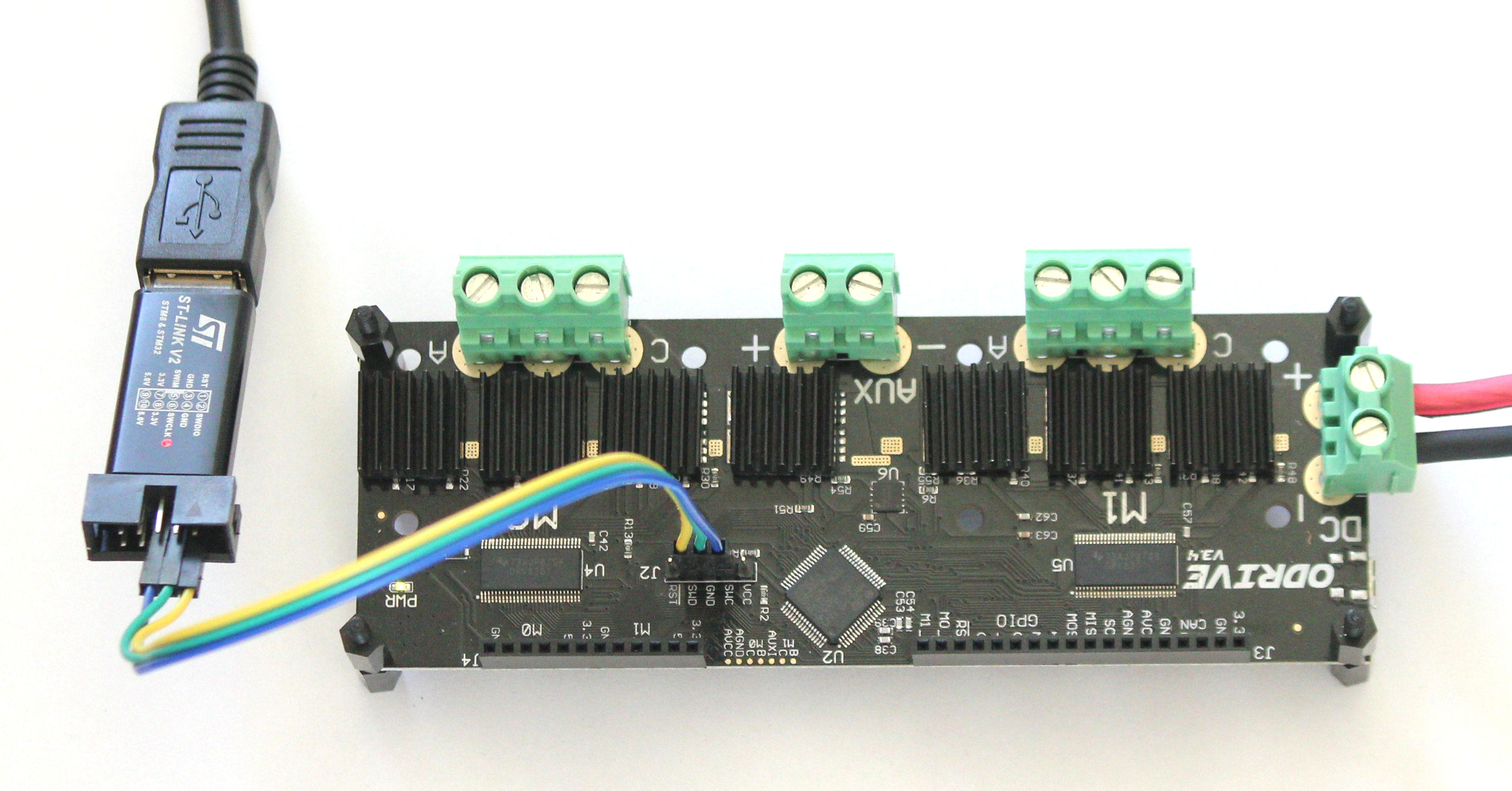
Stlink Wiring Diagram
and power up the ODrive.
Open up a terminal and navigate to the directory where the firmware is.
Run the following command (replace
ODriveFirmware_v3.4-24V.elfwith the name of your firmware file):openocd -f interface/stlink-v2.cfg -f target/stm32f4x.cfg -c init -c "reset halt" -c "flash write_image erase ODriveFirmware_v3.4-24V.elf" -c "reset run" -c exit
If everything worked correctly, you should see something similar to this towards the end of the printout:
wrote 262144 bytes from file ODriveFirmware_v3.4-24V.elf in 10.194110s (25.113 KiB/s)
If something doesn’t work, make sure
openocdis in yourPATHvariable, check that the wires are connected properly and try with elevated privileges.
Liveplotter
Liveplotter is used for the graphical plotting of odrive parameters (i.e. position) in real time. To start liveplotter, close any other instances of liveplotter and run
odrivetool liveplotter
from a new anaconda prompt window. By default two parameters are plotted on startup; the encoder position of axis 1 and axis 2.
In the below example the motors are running in closed_loop_control while they are being forced off position by hand.
To change what parameters are plotted open odrivetool (located in Anaconda3Scripts or ODrive-mastertools) with a text editor and modify the liveplotter function:
# If you want to plot different values, change them here.
# You can plot any number of values concurrently.
cancellation_token = start_liveplotter(lambda: [
    odrv0.axis0.encoder.pos_estimate,
    odrv0.axis1.encoder.pos_estimate,
])
For example, to plot the approximate motor torque [Nm] and the velocity [RPM] of axis0, you would modify the function to read:
# If you want to plot different values, change them here.
# You can plot any number of values concurrently.
cancellation_token = start_liveplotter(lambda: [
    ((odrv0.axis0.encoder.vel_estimate*60), # turns/s to rpm
    ((odrv0.axis0.motor.current_control.Iq_setpoint * my_odrive.axis0.motor.config.torque_constant), # Torque [Nm]
])
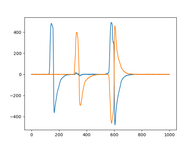
In the example below the motor is forced off axis by hand and held there. In response the motor controller increases the torque (orange line) to counteract this disturbance up to a peak of 500 N.cm at which point the motor current limit is reached. When the motor is released it returns back to its commanded position very quickly as can be seen by the spike in the motor velocity (blue line).

Liveplotter Torque Velocity Plot
To change the scale and sample rate of the plot modify the following parameters located at the beginning of utils.py (located in Anaconda3Libsite-packagesodrive):
data_rate = 100
plot_rate = 10
num_samples = 1000
For more examples on how to interact with the plotting functionality refer to these Matplotlib examples.
Liveplotter from Interactive odrivetool Instance
You can also run start_liveplotter(...) directly from the interactive odrivetool prompt.
This is useful if you want to issue commands or otherwise keep interacting with the odrive while plotting.
For example you can type the following directly into the interactive prompt:
start_liveplotter(lambda: [odrv0.axis0.encoder.pos_estimate])
Just like the examples above, you can list several parameters to plot separated by comma in the square brackets. In general, you can plot any variable that you are able to read like normal in odrivetool.