Endstops and Homing
By default, the ODrive assumes that your motor encoder’s zero position is the same as your machine’s zero position, but in real life this is rarely the case. In these systems it is useful to allow your motor to move until a physical or electronic device orders the system to stop. That endstop can be used as a known reference point. Once the ODrive has hit that position it may then want to move to a final zero, or home, position. The process of finding your machine’s zero position is known as homing.
ODrive supports the use of its GPIO pins to connect to phyiscal limit switches or other sensors that can serve as endstops.
Before you can home your machine, you must be able to adequately control your motor in AXIS_STATE_CLOSED_LOOP_CONTROL.
Endstop Configuration
Each axis supports two endstops: min_endstop and max_endstop.
For each endstop, the following properties are accessible through odrivetool:
Name |
Type |
Default |
|---|---|---|
gpio_num |
int |
0 |
offset |
float |
0.0 |
debounce_ms |
float |
50.0 |
enabled |
boolean |
false |
is_active_high |
boolean |
false |
gpio_num
The GPIO pin number, according to the silkscreen labels on ODrive. Set with these commands:
<odrv>.<axis>.max_endstop.config.gpio_num = <1, 2, 3, 4, 5, 6, 7, 8>
<odrv>.<axis>.min_endstop.config.gpio_num = <1, 2, 3, 4, 5, 6, 7, 8>
enabled
Enables/disables detection of the endstop. If disabled, homing and e-stop cannot take place. Set with:
<odrv>.<axis>.max_endstop.config.enabled = <True, False>
<odrv>.<axis>.min_endstop.config.enabled = <True, False>
offset
This is the position of the endstops on the relevant axis, in turns. For example, if you want a position command of 0 to represent a position 3 turns away from the endstop, the offset would be -3.0 (because the endstop is located at axis position -3.0).
<odrv>.<axis>.min_endstop.config.offset = <int>
This setting is only used for homing. Only the offset of the min_endstop is used.
debounce_ms
The debouncing time for this endstop. Most switches exhibit some sort of bounce, and this setting will help prevent the switch from triggering repeatedly.
It works for both HIGH and LOW transitions, regardless of the setting of is_active_high.
Debouncing is a good practice for digital inputs, read up on it here. debounce_ms has units of miliseconds.
<odrv>.<axis>.max_endstop.config.debounce_ms = <Float>
<odrv>.<axis>.min_endstop.config.debounce_ms = <Float>
is_active_high
This is how you configure the endstop to be either “NPN” or “PNP”.
An “NPN” configuration would be is_active_high = False whereas a PNP configuration is is_active_high = True.
Refer to the following table for more information:
Typically configuration 1 or 3 is preferred when using mechanical switches as the most common failure mode leaves the switch open.
GPIO Configuration
The GPIOs that are used for the endstops need to be configured according to the diagram below.
Assuming your endstop is connected to GPIO X:
Configuration 1, 2:
<odrv>.config.gpioX_mode = GPIO_MODE_DIGITAL_PULL_DOWNConfiguration 3, 4:
<odrv>.config.gpioX_mode = GPIO_MODE_DIGITAL_PULL_UP

Example
If we want to configure a 3D printer-style (configuration 4) minimum endstop for homing on GPIO 5 and we want our motor to move away from the endstop about a quarter turn, we would set:
<odrv>.config.gpio5_mode = GPIO_MODE_DIGITAL
<odrv>.<axis>.min_endstop.config.gpio_num = 5
<odrv>.<axis>.min_endstop.config.is_active_high = False
<odrv>.<axis>.min_endstop.config.offset = -0.25
<odrv>.<axis>.min_endstop.config.enabled = True
<odrv>.config.gpio5_mode = GPIO_MODE_DIGITAL_PULL_UP
Testing The Endstops
Once the endstops are configured you can test your endstops for correct functionality. Try activating your endstops and check the states of these variables through odrivetool:
<odrv>.<axis>.max_endstop.endstop_state
<odrv>.<axis>.min_endstop.endstop_state
A state of True means the switch is pressed. A state of False means the switch is NOT pressed. As simple as that. Give it a try. Click your switches, or put a magnet on your hall switch and see if the states change.
After testing, don’t forget to save and reboot:
<odrv>.save_configuration()
<odrv>.reboot()
Homing
There is one additional configuration parameter in controller.config specifically for the homing process:
Name |
Type |
Default |
|---|---|---|
homing_speed |
float |
0.25f |
homing_speed is the axis travel speed during homing, in [turns/second].
If you are using SPI based encoders and the axis is homing in the wrong direction, you can enter a negative value for the homing speed and a negative value for the minimum endstop offset.
Set the homing speed to 0.25 turns / sec:
odrv0.axis0.controller.config.homing_speed = 0.25
Performing the Homing Sequence
Homing is possible once the ODrive has closed-loop control over the axis. To trigger homing, we must enter:code:AXIS_STATE_HOMING. This starts the homing sequence, which works as follows:
The axis switches to
INPUT_MODE_VEL_RAMPThe axis ramps up to
homing_speedin the direction ofmin_endstopThe axis presses the
min_endstopThe axis switches to
INPUT_MODE_TRAP_TRAJThe axis moves to the home position in a controlled manner
It requires quite a few settings in addition to the endstop settings:
<odrv>.<axis>.controller.config.vel_ramp_rate
<odrv>.<axis>.trap_traj.config.vel_limit
<odrv>.<axis>.trap_traj.config.accel_limit
<odrv>.<axis>.trap_traj.config.decel_limit
We realize this is a little excessive and we will work towards minimizing the setup, but this works well for smooth and reliable behaviour for now.
Homing at Startup
It is possible to configure the odrive to enter homing immediately after startup. To enable homing at startup, the following must be configured:
<odrv>.<axis>.config.startup_homing = True
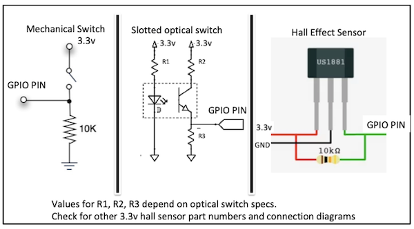
Additional Endstop Devices
In addition to phyiscal switches there are other options for wiring up your endstops - you will have to work out the details of connecting your device but here are some suggested approaches: