CAN Bus Guide
ODrive Pro, S1, and Micro all use a custom protocol called CANSimple.
This currently supports CAN 2.0b, as well as experimental support for CAN-FD (see config.can.data_baud_rate).
For more information, please refer to the CAN protocol page.
Note
This guide is intended for beginners to set up CAN on the ODrive and on their host device. We will be working with a Linux system as our host device, using Python, but the examples can be applied to any other systems.
Why use CAN?
CAN is convenient for its simple and robust Physical Layer (PHY) that requires only a twisted pair of wires and a 120ohm termination resistor at each end. It has low jitter and low latency, because there is no host computer. It is relatively fast (CAN 2.0b supports 1 Mbps). Messages are easy to configure and load with data. Transceivers and controllers are inexpensive and widely available, thanks to its use in automotive.
Hardware Setup
ODrive assumes the physical layer is a standard differential twisted pair in a linear bus configuration with 120 ohm termination resistance at each end. The CANH (High) and CANL (Low) pins are used for CAN communication. Connect CANH to CANH and CANL to CANL (found on the datasheet pinout (Pro, S1, Micro)) for all devices on the bus, and ensure you have a good ground between each node.
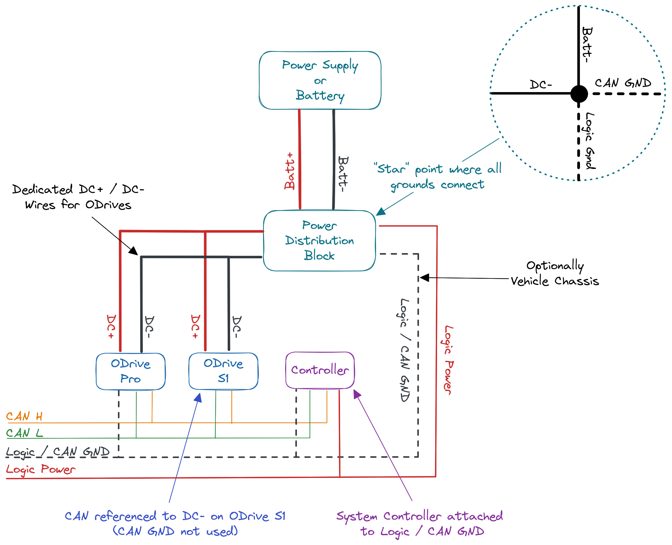
Semi-isolated CAN FD network
CAN transceiver is powered internally, but needs an external ground return.
CAN GND should be connected to the system’s star ground point: a galvanic connection between the CAN GND net and DC- net should be established at a single point across the entire system to prevent ground loops.
Advanced configurations
Fully isolated CAN:
Remove the 0ohm resistor jumpers R97 (powers CAN transceiver from ODrive 12V) and R96 (powers ODrive 12V from CAN 12V).
Remove CAN isolation:
Bridge the pads labeled R81. This will tie the CAN GND to the internal ODrive GND. Be wary of ground loops and noise in this configuration.
In this configuration we recommend only connecting CAN_H and CAN_L on the can header and not connecting to CAN_GND, similar to the non-isolated configuration on the ODrive S1.
Contact sales@odriverobotics.com to order customized builds in volume.
CAN is not isolated, CAN signals are referenced to DC-. Therefore you must connect your CAN bus ground to DC- at the system star point.
Optional 12V logic power input which is referenced to DC-.
ODrive S1 has a GND on the CAN IO headers (J16, J17), they are not connected to the rest of the ODrive - only to the other connector. You can use this to daisy chain your CAN ground without creating a ground loop through the ODrive.
CAN is not isolated, CAN signals are referenced to DC-. Therefore you must connect your CAN bus ground to DC- at the system star point.
ODrive Micro has a GND on the CAN IO headers (J2, J3), they are not connected to the rest of the ODrive - only to the other connector. You can use this to daisy chain your CAN ground without creating a ground loop through the ODrive.
Important
Make sure to connect CAN GND to DC- at the system ground star point.
Note
Many devices make use of a DE-9 (commonly mistakenly called DB-9) connector for CAN. The typical pinout is CANL on pin 2 and CANH on pin 7.
Important
If your ODrive is the “last” (furthest) device on the bus, you can use the on-board 120 Ohm termination resistor by switching the DIP switch to “CAN 120R”. Otherwise, add an external resistor. The nominal bus resistance should be 60 ohms between CANH and CANL.
Setting up the Host
On most host computers you need external hardware to communicate over CAN. For most applications, we recommend the ODrive USB-CAN adapter. Alternatively, for galvanic isolation and CAN-FD support you can use the PCAN-USB FD Adapter.
Note
To use the WebGUI over CAN on any platform (including Linux), an ODrive USB-CAN adapter must be used. An ODrive USB-CAN adapter is also required to use odrivetool over CAN on Windows or macOS (coming soon). odrivetool over CAN on Linux (coming soon) will work with any SocketCAN interface.
The ODrive USB-CAN adapter and the PCAN-USB FD Adapter work out of the box on Linux systems and you only need to enable it.
For Raspberry Pi and similar boards, there are CAN hats available, for example:
These require additional setup steps, see below.
Enable CAN Hat
Open the
/boot/firmware/config.txtwithsudo nano /boot/firmware/config.txt
At the bottom of the file, add the following:
dtparam=spi=on
dtoverlay=spi1-3cs
dtoverlay=mcp251xfd,spi0-0,oscillator=40000000,interrupt=25 # configure can0 interface
dtoverlay=mcp251xfd,spi1-0,oscillator=40000000,interrupt=24 # configure can1 interface
dtparam=spi=on
dtoverlay=spi0-hw-cs
dtoverlay=mcp2515-can0,oscillator=12000000,interrupt=25 # configure can0 interface
Important
Some SPI CAN hat variants have different oscillator crystals, make sure the value for
oscillator(12MHz here) matches the hardware you are using. If you’re not sure what value to use, the top of the oscillator will have the value printed on it in MHz.Reboot the device for these changes to take effect.
sudo reboot
Note
For more details regarding this process, checkout this in depth tutorial and this forum post
Enable CAN interface
Before you can use the CAN interface, it needs to be enabled with:
sudo ip link set can0 up type can bitrate 250000
This is required after every reboot. If this fails with RTNETLINK answers: Device or resource busy, the interface might already be up.
New since firmware version 0.6.11: The baudrate value 250000 (250 kbps) is given as an example. You can use any compatible value here and the ODrive will automatically detect it.
Setting up the ODrive (via USB)
The ODrive’s CAN interface is enabled by default. All you have to do is to assign a unique node ID to each ODrive on the bus so that they don’t conflict. For some applications you may also want to enable periodic feedback messages.
Under Configuration > Interfaces:
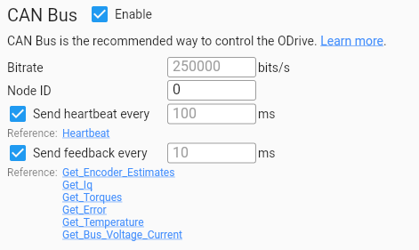
<odrv>.axis0.config.can.node_id= 0 # or 1, 2, …More on cyclic messages here.
Setting up the ODrive (CAN only)
This section describes how to set up an unconfigured ODrive in environments where only CAN communication is available, specifically for systems that do not have USB access.
Hint
If this is your first time using an ODrive, we recommend that you use the Web GUI first to familiarize yourself with the device and get a motor spinning. Since the GUI does not have CAN support yet, this requires a USB connection. Once it spins over USB you can follow this section to (re-)configure additional ODrives where USB is not available.
The process consists of three parts:
Bootstrapping CAN communication via CAN
Writing a previously configured set of configuration
Running calibration procedures
Bootstrapping CAN communication via CAN
⇒ New in Firmware 0.6.9
To bootstrap CAN communication, use can_enumerate.py to assign each ODrive to its function.
In the simplest use case, it will scan the CAN bus for any ODrives and assign a random node ID to each one. For each discovered ODrive, it will print the serial number and node ID that it picked.
python3 /path/to/can_enumerate.py --channel can0 --save-config
Example Output
Scanning for ODrives...
Discovered ODrive 335D377D3432 (unaddressed)
Assigning node ID 0 to 335D377D3432
Scan complete. Discovered 1 ODrives.
If you want control over which ODrive gets which ID, you can run the script in interactive mode.
To do so, pass pairs of label=node_id to the script (where label can be any user defined designation).
For example, if your ODrive has two wheels and you want to assign node ID 0 to the left wheel and node ID 1 to the right wheel:
python3 /path/to/can_enumerate.py --channel can0 left=0 right=1 --save-config
The script will then randomly pick one ODrive on the bus and blink its status LED. It will then ask the user which ODrive has a blinking LED and thereby know which node ID to assign to it. This is repeated for all ODrives.
For more options, see can_enumerate.py --help.
Writing configuration
Once the ODrives are addressed, you can write all the other configuration variables.
Prepare a file called
config.jsonthat has the following form:
{
  "config.dc_bus_overvoltage_trip_level": 40,
  "config.dc_max_negative_current": -10,
  "config.brake_resistor0.enable": true,
  "config.brake_resistor0.resistance": 2,
  "axis0.config.motor.motor_type": 0,
  ...
}
If you used the GUI for prototyping (see note above), you can export the set of configuration variables by going to Configuration > Apply & Calibrate, copying the Python snippet from there, and doing a bit of manual reformatting into JSON.
Download
flat_endpoints.jsoncorresponding to your ODrive and firmware version from this page.Run can_restore_config.py. For example:
python3 /path/to/can_restore_config.py --channel can0 --node-id 0 --endpoints-json /path/to/flat_endpoints.json --config config.json --save-configFor more options, see
can_restore_config.py --help.
Running calibration
Finally, to run the calibration sequence, you can use can_calibrate.py. For example:
python3 /path/to/can_calibrate.py --channel can0 --node-id 0 --save-config
For more options, see can_calibrate.py --help.
Your ODrive is now ready to spin a motor! See Code Examples for next steps.
Verifying Communcation
Once a node ID is assigned to an ODrive (see above), it will by default send a heartbeat message at 10Hz. We can confirm our ODrive communication is working by dumping the incoming CAN messages in the terminal:
sudo apt-get install can-utils # one-time install
candump can0 -xct z -n 10
This will read the first 10 messages from the ODrive and stop. If you’d like to see all messages, remove the -n 10 part (hit CTRL+C to exit).
The other flags (x, c, t) are adding extra information, colouring, and a timestamp, respectively.
candump can0 -xct z -n 10
(000.000000)  can0  RX - -  001   [8]  00 00 00 00 01 00 00 00
(000.001995)  can0  RX - -  021   [8]  00 00 00 00 08 00 00 00
(000.099978)  can0  RX - -  001   [8]  00 00 00 00 01 00 00 00
(000.101963)  can0  RX - -  021   [8]  00 00 00 00 08 00 00 00
(000.199988)  can0  RX - -  001   [8]  00 00 00 00 01 00 00 00
(000.201980)  can0  RX - -  021   [8]  00 00 00 00 08 00 00 00
(000.299986)  can0  RX - -  001   [8]  00 00 00 00 01 00 00 00
(000.301976)  can0  RX - -  021   [8]  00 00 00 00 08 00 00 00
(000.399986)  can0  RX - -  001   [8]  00 00 00 00 01 00 00 00
(000.401972)  can0  RX - -  021   [8]  00 00 00 00 08 00 00 00
Alternatively, if you have python can installed (pip3 install python-can), you can use the can.viewer script:
python3 -m can.viewer -c "can0" -i "socketcan" which will give you a nice readout.
Code Examples
This section uses Python to illustrate how CAN communication with the ODrive works. You can download and run the full examples as-is to get started, and then go from there based on your needs. The examples are kept simple so that if you intend to use something other than Python, you can easily transfer them to your target language and platform.
Intro: Read Heartbeat
Make sure all dependancies are install
pip3 install python-can
Create a CAN bus object and flush old messages
Define the heartbeat message ID
node_id = 0 # must match `<odrv>.axis0.config.can.node_id`. The default is 0.
cmd_id = 0x01 # heartbeat command ID
message_id = (node_id << 5 | cmd_id)
Note
CANSimple separates the CAN message ID into two parts: An axis ID and a command ID. Please refer to the CANSimple page for more information.
Wait for the heartbeat, and print results
import struct

for msg in bus:
  if msg.arbitration_id == message_id
      error, state, result, traj_done = struct.unpack('<IBBB', bytes(msg.data[:7]))
      break
print(error, state, result, traj_done)
Closed Loop Control
Important
Make sure your ODrive is fully connected and configured for closed loop control before continuing (this will require a USB connection). If you haven’t already, please see the Getting Started guide or the GUI Wizard to complete this step. Once finished, the USB connect is no longer required.
Make sure all dependancies are installed
pip3 install python-can
Create a CAN bus object and flush old messages
Put axis into closed loop control state
import struct

bus.send(can.Message(
    arbitration_id=(node_id << 5 | 0x07), # 0x07: Set_Axis_State
    data=struct.pack('<I', 8), # 8: AxisState.CLOSED_LOOP_CONTROL
    is_extended_id=False
))
Wait for axis to enter closed loop control by scanning heartbeat messages
for msg in bus:
    if msg.arbitration_id == (node_id << 5 | 0x01): # 0x01: Heartbeat
        error, state, result, traj_done = struct.unpack('<IBBB', bytes(msg.data[:7]))
        if state == 8: # 8: AxisState.CLOSED_LOOP_CONTROL
            break
Set velocity to 1.0 turns/s. See also Set_Input_Vel.
bus.send(can.Message(
    arbitration_id=(node_id << 5 | 0x0d), # 0x0d: Set_Input_Vel
    data=struct.pack('<ff', 1.0, 0.0), # 1.0: velocity, 0.0: torque feedforward
    is_extended_id=False
))
Print encoder feedback. See also Get_Encoder_Estimates.
Note that the ODrive sends the Get_Encoder_Estimates message periodically by default without explicit requests. To receive other feedback in the same way, see Cyclic Messages.
Arbitrary Parameter Access
If the predefined CAN messages do not cover your needs, this example describes how to read or write any parameter that is acessible from the GUI or odrivetool.
Every parameter is identified by a number. This number can change across firmware and hardware versions. There a json file available for this name-to-id mapping for every release of the firmware, for every supported hardware.
Download flat_endpoints.json from this page.
Load flat_endpoints.json
Define some constants we’re going to use further down:
OPCODE_READ = 0x00
OPCODE_WRITE = 0x01

# See https://docs.python.org/3/library/struct.html#format-characters
format_lookup = {
    'bool': '?',
    'uint8': 'B', 'int8': 'b',
    'uint16': 'H', 'int16': 'h',
    'uint32': 'I', 'int32': 'i',
    'uint64': 'Q', 'int64': 'q',
    'float': 'f'
}

node_id = 0 # must match the configured node_id on your ODrive (default 0)
Initialize the
busobject as shown in Intro: Read Heartbeat.Verify that the ODrive’s hardware and firmware are what we expect.
This is an important safety measure because the endpoints ID in flat_endpoints.json can change with every firmware and hardware version.
# Flush CAN RX buffer so there are no more old pending messages
while not (bus.recv(timeout=0) is None): pass

# Send read command
bus.send(can.Message(
    arbitration_id=(node_id << 5 | 0x00), # 0x00: Get_Version
    data=b'',
    is_extended_id=False
))

# Await reply
for msg in bus:
    if msg.is_rx and msg.arbitration_id == (node_id << 5 | 0x00): # 0x00: Get_Version
        break

import struct
_, hw_product_line, hw_version, hw_variant, fw_major, fw_minor, fw_revision, fw_unreleased = struct.unpack('<BBBBBBBB', msg.data)

# If one of these asserts fail, you're probably not using the right flat_endpoints.json file
assert endpoint_data['fw_version'] == f"{fw_major}.{fw_minor}.{fw_revision}"
assert endpoint_data['hw_version'] == f"{hw_product_line}.{hw_version}.{hw_variant}"
Write parameter
import struct

path = 'axis0.controller.config.vel_integrator_limit'
value_to_write = 1.234

# Convert path to endpoint ID
endpoint_id = endpoints[path]['id']
endpoint_type = endpoints[path]['type']

# Send write command
bus.send(can.Message(
    arbitration_id=(node_id << 5 | 0x04), # 0x04: RxSdo
    data=struct.pack('<BHB' + format_lookup[endpoint_type], OPCODE_WRITE, endpoint_id, 0, value_to_write),
    is_extended_id=False
))
Raw messages, assuming
node_id = 0,endpoint_id = 0x0182,value_to_write = 1.234:0x004 00 82 01 01 b6 f3 9d 3f
Read parameter
import struct

path = 'axis0.controller.config.vel_integrator_limit'

# Convert path to endpoint ID
endpoint_id = endpoints[path]['id']
endpoint_type = endpoints[path]['type']

# Flush CAN RX buffer so there are no more old pending messages
while not (bus.recv(timeout=0) is None): pass

# Send read command
bus.send(can.Message(
    arbitration_id=(node_id << 5 | 0x04), # 0x04: RxSdo
    data=struct.pack('<BHB', OPCODE_READ, endpoint_id, 0),
    is_extended_id=False
))

# Await reply
for msg in bus:
    if msg.is_rx and msg.arbitration_id == (node_id << 5 | 0x05): # 0x05: TxSdo
        break

# Unpack and print reply
_, _, _, return_value = struct.unpack_from('<BHB' + format_lookup[endpoint_type], msg.data)
print(f"received: {return_value}")
Raw messages, assuming
node_id = 0,endpoint_id = 0x0182,return_value = inf:0x004 00 82 01 00 0x005 00 82 01 00 00 00 80 7f
Function call
import struct

path = "save_configuration"

# Convert path to endpoint ID
endpoint_id = endpoints[path]['id']

bus.send(can.Message(
    arbitration_id=(node_id << 5 | 0x04), # 0x04: RxSdo
    data=struct.pack('<BHB', OPCODE_WRITE, endpoint_id, 0),
    is_extended_id=False
))
Raw messages, assuming
node_id = 0,endpoint_id = 0x0253:0x004 01 53 02 00
Troubleshooting
RTNETLINK answers: Device or resource busyThe CAN interface may already be started. To be sure, you can disable it with
sudo ip link set can0 up.can.CanError: Error receiving: [Errno 100] Network is downStart the CAN interface as shown in Enable CAN interface.
NVIDIA JetPack 6 users: By default the kernel comes without SocketCAN support. The SocketCAN drivers can be installed from this repository: https://github.com/slamcore/slamcore-dkms.