Controller
Structure
The motor controller is a cascaded style position, velocity and current control loop, as per the diagram below. When the control mode is set to position control, the whole loop runs. When running in velocity control mode, the position control part is removed and the velocity command is fed directly in to the second stage input. In torque control mode, only the current controller is used.
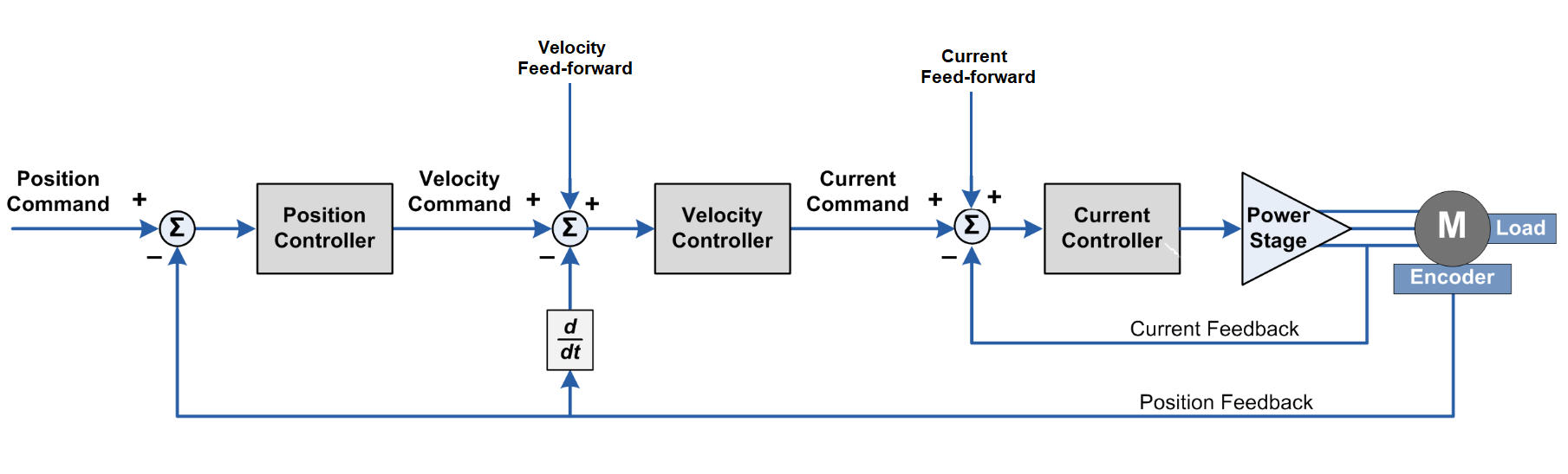
Cascaded position and velocity I loops
Each stage of the control loop is a variation on a PID controller. A PID controller is a mathematical model that can be adapted to control a wide variety of systems. This flexibility is essential as it allows the ODrive to be used to control all kinds of mechanical systems.
Note
The controller has been updated to use torque in Newton-meters instead of current at the “system” level.
There is a torque_constant parameter which converts between torque and current, after which the rest of this explanation still holds.
Position Control loop
The position controller is a P loop with a single proportional gain,
pos_error = pos_setpoint - pos_feedback,
  vel_cmd = pos_error * pos_gain + vel_feedforward.
Velocity Control Loop
The velocity controller is a PI loop where
        vel_error = vel_cmd - vel_feedback,
current_integral += vel_error * vel_integrator gain,
      current_cmd = vel_error * vel_gain + current_integral + current_feedforward.
Current Control Loop
The current controller is also a PI loop,
    current_error = current_cmd - current_feedback,
voltage_integral += current_error * current_integrator gain,
      voltage_cmd = current_error * current_gain + voltage_integral + ...
              ... + voltage_feedforward (when we have motor model).
Note
current_gain and current_integrator_gain are automatically set according to config.motor.current_control_bandwidth
Control Modes
Filtered Position Control
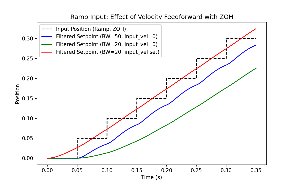
Asking the ODrive controller to go as hard as it can to raw setpoints may result in jerky movement. This is because the ODrive uses Zero Order Hold (ZOH) to retain the value between each sent command data. Even if you are using a continuous trajectory generated from an external source, if that is sent at a modest frequency, the ODrive may chase each stair in the incoming staircase in a jerky way. You can use the second order position filter to smooth out the trajectory.
A good starting point for tuning the filter bandwidth is to set it to the same value as your command sending frequency. For example, if you are sending a position command at 20Hz, set the filter bandwidth to 20.0 [/sec].
You may also set the velocity feed forward in order to significantly reduce the filter lag. See Set_Input_Pos.
odrv0.axis0.controller.config.input_filter_bandwidth = 20.0 # Set the filter bandwidth [1/s]
odrv0.axis0.controller.config.input_mode = InputMode.POS_FILTER # Activate the setpoint filter
odrv0.axis0.controller.input_pos = 1 # control the position [turns]
Trajectory Control
See the usage section for details. This mode lets you smoothly accelerate, coast, and decelerate the axis from one position to another. With raw position control, the controller simply tries to go to the setpoint as quickly as possible. Using a trajectory lets you tune the feedback gains more aggressively to reject disturbance, while keeping smooth motion.
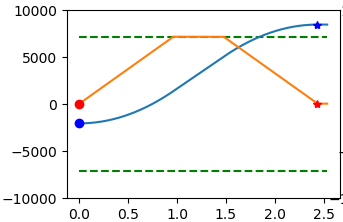
Position (blue) and velocity (orange) vs. time using trajectory control.
Note
Trajectory control is not compatible with circular mode
(<axis>.controller.config.circular_setpoints).
Parameters
odrv0.axis0.trap_traj.config.vel_limit = <Float>
odrv0.axis0.trap_traj.config.accel_limit = <Float>
odrv0.axis0.trap_traj.config.decel_limit = <Float>
odrv0.axis0.controller.config.inertia = <Float>
vel_limitis the maximum planned trajectory speed. This sets your coasting speed.accel_limitis the maximum acceleration in turns / sec^2decel_limitis the maximum deceleration in turns / sec^2controller.config.inertiais a value which correlates acceleration (in turns / sec^2) and motor torque. It is 0 by default. It is optional, but can improve response of your system if correctly tuned. Keep in mind this will need to change with the load / mass of your system.
Note
All values should be strictly positive (>= 0).
Keep in mind that you must still set your safety limits as before. It is recommended you set these a little higher ( > 10%) than the planner values, to give the controller enough control authority.
odrv0.axis0.config.motor.current_soft_max = <Float>
odrv0.axis0.controller.config.vel_limit = <Float>
Usage
Make sure you are in position control mode. To activate the trajectory module, set the input mode to trajectory:
odrv0.axis0.controller.config.input_mode = InputMode.TRAP_TRAJ
Simply send a position command to execute the move:
odrv0.axis0.controller.input_pos = <Float>
Use the move_incremental function to move to a relative position.
odrv0.axis0.controller.move_incremental(pos_increment, from_goal_point)
To set the goal relative to the current actual position, use from_goal_point = False
To set the goal relative to the previous destination, use from_goal_point = True
You can also execute a move with the appropriate ascii command.
Circular Position Control
To enable Circular position control, set
odrv0.axis0.controller.config.circular_setpoints = True
This mode is useful for continuous incremental position movement.
For example a robot rolling indefinitely, or an extruder motor or conveyor belt moving with controlled increments indefinitely.
In the regular position mode, the input_pos would grow to a very large value and would lose precision due to floating point rounding.
In this mode, the controller will try to track the position within only one turn of the motor. Specifically, input_pos is expected in the range [0, 1).
If the input_pos is incremented to outside this range (say via step/dir input), it is automatically wrapped around into the correct value.
Note that in this mode encoder.pos_circular is used for feedback instead of encoder.pos_estimate.
If you try to increment the axis with a large step in one go that exceeds 1 turn, the motor will go to the same angle around the wrong way. This is also the case if there is a large disturbance. If you have an application where you would like to handle larger steps, you can use a larger circular range. Set
odrv0.axis0.controller.config.circular_setpoint_range = <N>
Choose N to give you an appropriate circular space for your application.
Velocity Control
Set the control mode
odrv0.axis0.controller.config.control_mode = ControlMode.VELOCITY_CONTROL
You can now control the velocity [turn/s] with
odrv0.axis0.controller.input_vel = 1
Ramped Velocity Control
Adds an acceleration limit to the velocity setpoint, set via vel_ramp_rate
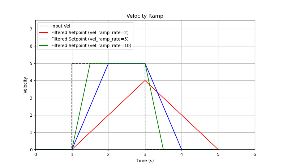
A step change in the velocity setpoint, starting from rest, showing the effect of various vel_ramp_rate values.
Set the control mode
odrv0.axis0.controller.config.control_mode = ControlMode.VELOCITY_CONTROL
Set the velocity ramp rate (acceleration in turn/s^2):
odrv0.axis0.controller.config.vel_ramp_rate = 0.5
Activate the ramped velocity mode:
odrv0.axis0.controller.config.input_mode = InputMode.VEL_RAMP
You can now control the velocity (turn/s) with
odrv0.axis0.controller.input_vel = 1
Torque Control
Set the control mode
odrv0.axis0.controller.config.control_mode = ControlMode.TORQUE_CONTROL
Set the torque constant, e.g.:
# Approximately 8.23 / Kv where Kv is in the units [rpm / V]
odrv0.axis0.config.motor.torque_constant = 8.23 / 150
You can now control the torque (Nm) with e.g.
odrv0.axis0.controller.input_torque = 0.1
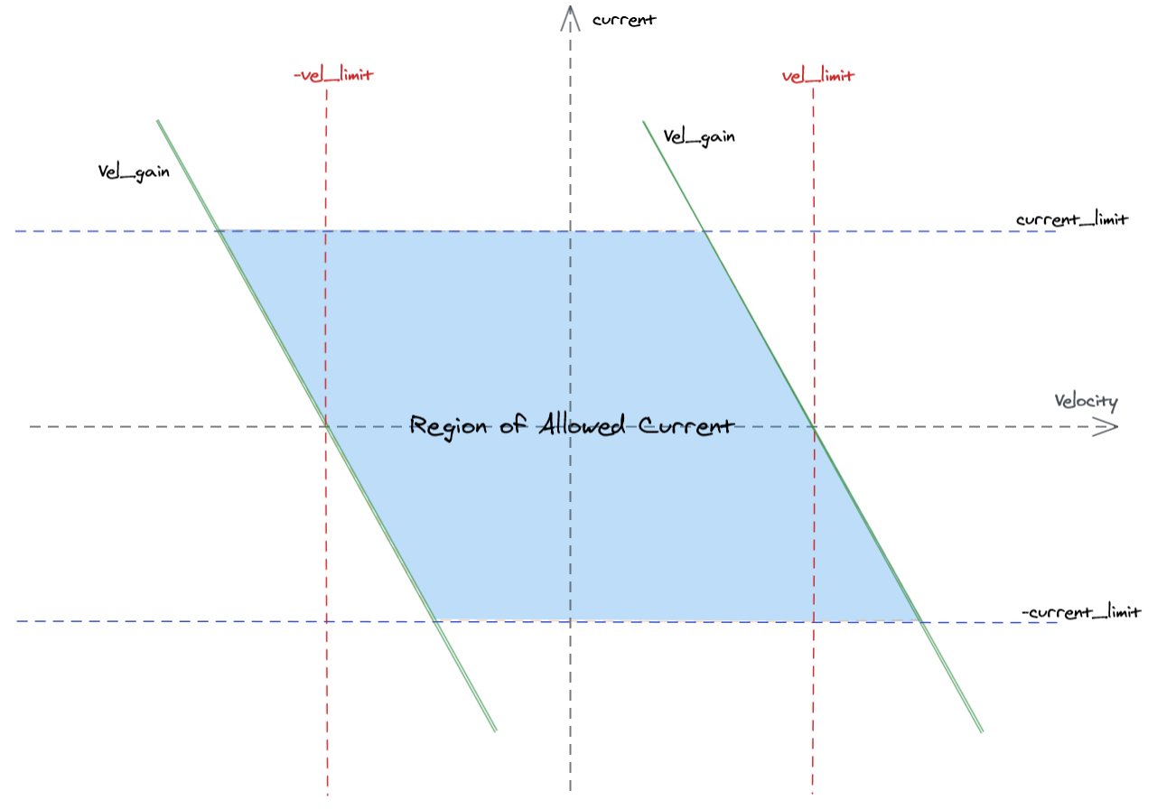
Note
For safety reasons, the torque mode velocity limiter is enabled by default.
This works by reducing the torque of the motor according to vel_limit and vel_gain, as shown below.
Please note that with the default settings, torque will be limited even at 0 rpm.
The torque mode velocity limiter can be completely disabled by setting:
odrv0.axis0.controller.config.enable_torque_mode_vel_limit = False
Position Reference Frame
The ODrive interprets all position commands with respect to <axis>.pos_estimate. That means when the user commands a position setpoint of 0.123, the ODrive tries to move the axis such that <axis>.pos_estimate becomes 0.123.
The physical position to which that corresponds to, depends on how the position reference frame is configured. The following subsections describe the available options.
Startup-Relative Reference Frame
This is the default configuration. A position of 0.0 corresponds to the physical position at which the ODrive started up. This mode useful for sending incremental position commands (“move 2 turns forward”).
This mode is selected by seting <axis>.controller.config.absolute_setpoints to False.
Homed Reference Frame
This reference frame is defined by electrical end-switches, which the ODrive can drive into. The end stop position is configured by the user, therefore the ODrive knows where it is in the homed reference frame as soon as it observes a signal on the end stop.
This mode is commonly used for axes that have a limited physical motion range and sensors at the end of the motion range.
To use this mode:
Set
<axis>.controller.config.absolute_setpoints=True.Configure
<axis>.min_endstop(see Endstops/Homing for more information)On every startup, run
<axis>.requested_state=AxisState.HOMING. Alternatively, you can set<axis>.config.startup_homing=True.
Note
After powering up or rebooting the ODrive, an attempt to run closed loop position control without running the homing procedure first, will be rejected by the ODrive with an error.
Custom User Reference Frame
The reference frame is defined by the user, based on external information.
This mode is useful if the user wants to implement a custom homing procedure or has some other way of determining the axis position, which is not natively supported by the ODrive (for example a vision-based approach).
To use this mode, simply write the current axis position to <axis>.pos_estimate. This is typically done once every time the ODrive powers up or reboots.
For improved safety, it is also recommended to set <axis>.controller.config.absolute_setpoints to True.
This makes the ODrive reject position control commands after startup until <axis>.pos_estimate has been set.
Absolute Encoder Reference Frame
If you’re using an absolute encoder on a multi-turn axis, you can use that encoder as a reference frame, under these conditions:
If you don’t mind if the reference frame shifts by integer encoder turn counts between reboots.
Or if you’re able to guarantee the approximate startup position within +- half of an encoder turn.
Why these conditions?
Even though the ODrive knows the encoder angle immediately at startup, it can in general not know the absolute position on a multi-turn axis. For example, if your axis has a motion range of five turns, there are five possible axis positions that any known encoder angle can correspond to.
However if the user is able to guarantee the approximate startup position within +- half of an encoder turn, the ODrive can combine this information with the measured encoder angle to determine the exact absolute axis position at startup without homing.
The following example shows how to configure this feature. The example assumes that your ODrive is already configured for (relative) position control.
odrv0.axis0.pos_vel_mapper.config.offset= 0.0 # change this if you want the meaning of "axis position zero" to differ from the encoder's zeroodrv0.axis0.pos_vel_mapper.config.offset_valid= Trueodrv0.axis0.pos_vel_mapper.config.approx_init_pos= 0.0 # change this if the guaranteed startup range is different from [-0.5, +0.5]. This is in the axis reference frame (see offset above).odrv0.axis0.pos_vel_mapper.config.approx_init_pos_valid= Trueodrv0.axis0.controller.config.absolute_setpoints= True
This example sets both offset and approx_init_pos to 0.0. While this might not represent your final configuration, it’s generally easier to begin with these settings. After executing odrv0.save_configuration(), the position estimate <axis>.pos_estimate will be immediately available without needing a homing procedure.
At this point, you can examine the <axis>.pos_estimate output to better understand if you need to adjust the offset (should you wish to shift the setpoint zero position) or alter the approx_init_pos (if the center of the startup range needs refining).
Absolute Encoder Reference Frame (circular)
If you’re using an absolute encoder and don’t care about turn count, you can use Circular Position Control and initialize the reference frame based on the encoder angle.
Note that in this mode, the position setpoints are interpreted in a circular space and the axis moves in whichever direction is closer to the setpoint.
To use this mode:
Set
odrv0.axis0.controller.config.circular_setpoints = TrueSet
odrv0.axis0.pos_vel_mapper.config.offset_valid = TrueCall
odrv0.save_configuration().
Index-based Reference Frame
Some incremental encoders have an index signal that can be used to align the position reference frame. This requires an index search on every startup to initialize the position estimate.
To use this mode:
Configure the
pos_vel_mapper:<axis>.pos_vel_mapper.config.index_gpio= <N><axis>.pos_vel_mapper.config.use_index_gpio= True<axis>.pos_vel_mapper.config.index_offset= 0<axis>.pos_vel_mapper.config.index_offset_valid= TrueFollow the general steps for Index Search.
Spinout Detection
Spinout Detection continuously monitors the correlation between the commanded mechanical power and the actual electrical power sent to the motor. A large discrepancy between these values can indicate a spinout situation, where the ODrive self-detects a lack of proper control over the motor and disarms to ensure safety. If the discrepancy exceeds the specified thresholds, a SPINOUT_DETECTED error is triggered.
Here are key scenarios that can cause spinout errors:
Encoder Slippage: Encoder slippage refers to a situation where a shaft-mounted encoder (such as AMT10 and AMT21) loses its position due to gradual shaft slippage. Improve encoder mounting to eliminate the possibility of slippage. With the AMT10 and AMT21 specifically, make sure to strictly follow the included mounting instructions and use the included mounting tools. Afterwards, try re-running
ENCODER_OFFSET_CALIBRATION.Encoder Offset Calibration: Spinout errors can occur due to poor encoder calibration. Reduce external non-friction load on the motor/encoder assembly. E.g. a mobile robot should be lifted off the ground. A robot arm should not fight against gravity. Then try re-running
ENCODER_OFFSET_CALIBRATION.Mechanical Changes: When disassembling the motor-encoder assembly and reassemblying it, the alignment between encoder and motor usually changes. It is therefore necessary to re-run
ENCODER_OFFSET_CALIBRATIONafterwards. Forgetting to do so can cause a spinout error.Low-resolution encoders and rapid accelerations: With low-resolution encoders like Hall effect encoders, and/or during rapid accelerations, false spinout errors may occur even with a properly calibrated encoder.
If you are sure that the the spinout error is not due to a real spinout, you can adjust these thresholds:
Increase
<axis>.controller.config.spinout_electrical_power_thresholdto a higher value (e.g., from 20 to 100).Make
<axis>.controller.config.spinout_mechanical_power_thresholdmore negative (e.g., from -20 to -100).
These adjustments widen the acceptable discrepancy between sensed electrical and mechanical power, reducing the likelihood of false spinout detection. For situations where spinout detection is not crucial, setting the thresholds very high (e.g. +9999 and -9999 respectively) will effectively disable this feature. Please note that this removes a crucial part of the ODrive’s safety monitoring, and should only be done if there’s the utmost confidence that the encoder is correctly and reliably coupled to the motor.