ODrive Regen Clamp Datasheet
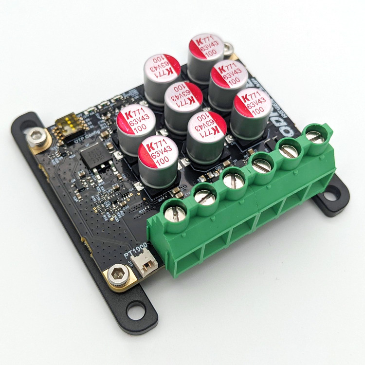
The ODrive Regen Clamp provides a high-performance braking energy management solution for ODrives without an external brake resistor. It automatically detects power regeneration from downstream motor drives, and diverts excess energy to an external brake resistor.
It incorporates a high-performance ideal diode circuit to allow current to flow to downstream ODrives and devices, while detecting and blocking regenerated current, dissipating it through an external resistor.
The Regen Clamp additionally has a connector for an optional PT1000 RTD temperature sensor, to allow for overtemperature protection of the external brake resistor.
The Regen Clamp is compatible with the S1 heatspreader plate.
Electromechanical Specifications
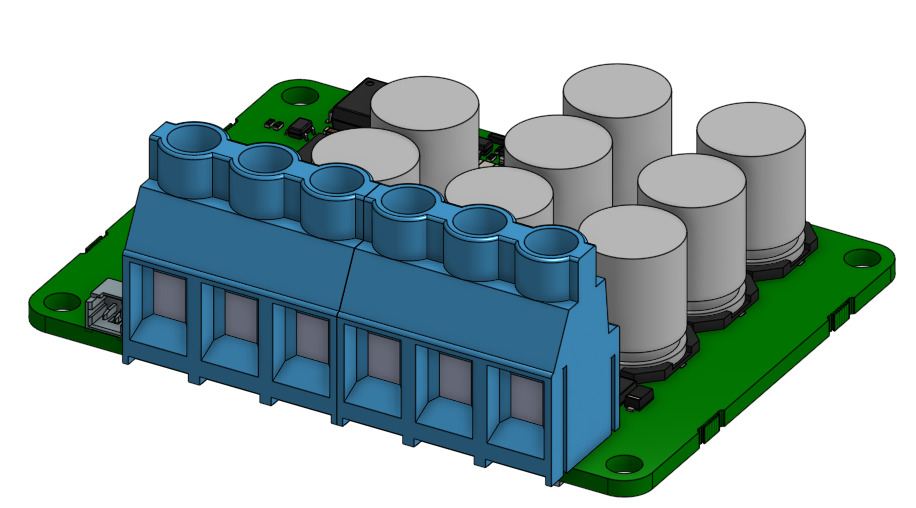
CAD
The Regen Clamp CAD model is available here.
Electrical
Note
All specifications are in 0◦C ≤ TA≤ 40◦C unless otherwise noted.
Specification |
Min. |
Typ. |
Max. |
Units |
Conditions and Notes |
|---|---|---|---|---|---|
DC Voltage |
10 |
58 |
V |
||
Forward Current |
20 80 120 |
A |
Free air (TA 25°C) With heatspreader plate Peak |
||
Brake Current |
20 40 80 |
A |
Free air (TA 25°C) With heatspreader plate Peak |
||
Brake Activation Voltage |
2.35 |
2.50 |
V |
Vout over Vin |
|
Brake Deactivation Voltage |
0.5 |
0.75 |
V |
Vout over Vin |
|
Onboard Capacitance |
800 |
uF |
Low ESL/ESR |
||
Forward Voltage Drop |
10 |
25 |
125 |
mV |
Under 55mV up to 53A I fwd |
Switching Frequency |
0 |
15 |
kHz |
Dependent on Rbrake and Iregen |
|
ESD Protection |
±30 ±2 |
kV |
Power Lines, IEC 61000-4-2 PT1000 Input, HBM |
Physical
Specification |
Value |
Units |
Notes |
|---|---|---|---|
Mass |
28 47 79 |
g |
Bare Board (solder pads) w/ Screw Terminals w/ Heat Spreader |
Width Length Height |
66 50 15.3 |
mm |
|
Mounting |
PCB Heat Spreader |
4x M3, 60mm x 44mm pattern (horizontal, vertical) 4x M4, 70mm x 70mm pattern |
|
Connectors
Connector mating receptacles and crimps.
Connector |
Description |
Connector P/N |
Mating Receptacle |
Mating Crimp |
Precrimped Wire P/N |
|---|---|---|---|---|---|
Power |
Optional Screw Terminal |
TB005-762-06BE |
N/A |
N/A |
N/A |
J11 |
PT1000 RTD Connector |
530480210 |
0510210200 |
0501258000 |
2149211214 |
Pinout
Power Pads
Important
IN+-/OUT+- cannot tolerate reversed polarity, verify all power pad connections before energizing.
Pad |
Description |
|---|---|
R- |
Brake resistor output |
R+ |
Brake resistor output |
OUT+ |
Power output, to motor drivers |
OUT- |
Power ground |
IN- |
Power ground |
IN+ |
Power input, from supply |
Usage & Wiring
The Regen Clamp is designed to sit between a “upstream” power source, such as DC power supply, and one or more “downstream” devices that may regenerate energy (such as ODrives without brake resistors, and other motor drivers). It monitors the direction of current between the supply and the downstream devices - if the downstream devices are drawing power from the supply, it will pass this current as normal. However, if it senses that the downstream devices are regenerating power back to the supply, it will divert all excess regenerated energy to the external brake resistor.
This enables any (sufficiently powerful) DC power supply to be used with all ODrives and motor drivers, even those without brake resistors.
Typical usage of the Regen Clamp only requires the input power supply to be wired to the IN+/IN- terminals, one or more downstream devices to be wired to the OUT+/OUT- terminals, and a suitable brake resistor (see brake resistor selection) to be wired to the R+/R- terminals.
Optionally, an external temperature sensor can be used to protect the brake resistor from overheating. See Overtemperature Protection.
Important
The Regen Clamp has a large amount of onboard capacitance. Connecting it directly to a powered battery or supply can result in large inrush currents, causing sparking and possible damage to the Regen Clamp, downstream devices, or power supply or battery. Only wire to a DC supply while it is powered off, and wire to batteries using an antispark connector, NTC inrush limiter, or other inrush current limiting device.
Example wiring:

Status LEDs
LED |
Description |
|---|---|
Green |
The Regen Clamp is powered |
Blue |
Regenerated energy is being dissipated across the brake resistor |
Red |
The RTD sensor / brake resistor is over the temperature threshold |
Overtemperature Protection
The Regen Clamp supports an external PT1000 RTD temperature sensor to sense the brake resistor’s temperature and implement overtemperature protection (OTP). Multiple OTP trip thresholds are available, from 120°C to 475°C. The PT1000 should be thermally bonded to the brake resistor, using a suitably rated thermal grease or adhesive. Note that only specifically PT1000 RTD sensors are supported, and not thermistors or thermocouples.
In the event the sensed temperature reaches the OTP threshold, the red LED will turn on, and the Regen Clamp will disable itself until the temperature falls 10°C below the OTP threshold. That is to say, if the OTP threshold is set to 325°C (S1=ON, S2=OFF, S3=ON), and the brake resistor/PT1000 RTD sensor passes 325°C, the Regen Clamp will disable until the sensed temperature falls below 315°C.
Important
Please ensure that both the PT1000 RTD sensor and your brake resistor of choice are rated to the selected overtemperature trip threshold
The overtemperature protection (OTP) is enabled and configured using the DIP switch array in the upper left corner of the top of the board.
To enable OTP, slide the topmost switch, labeled “OTP EN” to the “ON” side (and slide to the “OFF” side to disable).
The three other switches, labeled S1, S2, and S3, are used for setting the OTP trip threshold.
S1 Setting |
S2 Setting |
S3 Setting |
OTP Threshold |
|---|---|---|---|
OFF |
OFF |
OFF |
120°C |
ON |
OFF |
OFF |
150°C |
OFF |
ON |
OFF |
180°C |
ON |
ON |
OFF |
220°C |
OFF |
OFF |
ON |
265°C |
ON |
OFF |
ON |
325°C |
OFF |
ON |
ON |
385°C |
ON |
ON |
ON |
475°C |
Brake Resistor Selection
To select an optimal brake resistor value, a few constraints must be obeyed:
Let \(V\) be the nominal bus voltage, and \(R_{brake}\) be the brake resistor resistance.
First, the maximum current through the Regen Clamp’s brake driver must stay under 80A peak:
Second, the brake resistor must be able to dissipate all regenerated current from the motor. Regenerated current can be estimated by dividing the maximum motor power by the bus voltage. Maximum motor power can be calculated with:
Where \(I_{max}\) is the motor’s current_soft_max, and \(\omega_{max}\) is the 60*vel_limit (i.e. max velocity in RPM).
Maximum regenerated current can be found with:
In order to ensure all regenerated power can be dissipated, the resistor must dissipate more than the maximum regenerated current at the bus voltage:
Given these two constraints, an available brake resistor can be selected. Note that the average regenerated power must be lower than the brake resistor’s power rating, or dangerous overtemperature can occur (without overtemperature protection).
Example
Let’s say we have 24V power supply, with a M8325s 100Kv motor. The ODrive is configured with a current_soft_max of 50A, and a vel_limit of 30 rev/s (1800 RPM).
First, we can calculate the lowest resistance brake resistor value in order to not exceed the 80A current limit on the Regen Clamp’s brake driver:
Next, we calculate our motor’s maximum regenerated power:
If we’re operating on a 24V bus, then this means we will regenerate a theoretical maximum of:
Now we can find the highest resistance brake resistor value needed to dissipate the full 32.45A.
So now we know \(0.3 \Omega \leq R_{brake} \leq 0.74 \Omega\). From here, we could select a standard, commonly available value in this range - for instance, 0.5 ohm power resistors are quite common.
Consideration must be given to the brake resistor’s power rating - most applications don’t require constant regeneration, and so a lower rated (e.g. 25W or 100W rated) resistor would likely be adequate for this application, depending on the regeneration duty cycle. If you think your brake resistor may get hot, make sure to utilize overtemperature protection.