Designing for Magnetic Encoders
Overview
Magnetic encoders are one type of sensor that can be used to design and operate responsive and effective mechanisms.
Nearly any brushless system seeking to achieve precise position, velocity, or torque control needs an encoder of some sort. The ODrive supports a wide variety of encoders, and magnetic encoders are frequently a go-to choice for their low cost, ease of use, and absolute positioning. However, magnetic encoders come with a set of design considerations and constraints that must be respected to produce an accurate, reliable system.
Let’s review some best practices and common pitfalls when using a magnetic encoder with your ODrive, and how to design the best system possible.
Quick Reference:
Magnet type: Diametrically polarized neodymium, grade N42 or higher (N45SH recommended).
Spacing: Typical 0.5–3mm spacing between magnet and encoder IC.
Alignment tolerance: Maximum recommended misalignment of ±0.5mm. Magnet and encoder IC surfaces must remain parallel.
Mounting methods: Securely press-fit, clamp, or glue magnets to the motor shaft. Ensure ±0.5mm alignment between magnet and shaft.
Materials: Avoid ferromagnetic materials within 2mm of the encoder. Ferromagnetic magnet holders must be used with a stronger/thicker magnet.
Validation:
<odrv>.onboard_encoder0.get_field_strength()should return ≥ 0.045 when using an ODrive’s onboard magnetic encoder. The OA1 encoder uses a green LED to indicate sufficient field strength.Harmonic compensation: Consider using harmonic compensation if experiencing current or velocity ripple proportional to motor speed.
Primer
What are we working with?
The ODrive S1, ODrive Pro, and ODrive Micro have a built-in MPS MA702 absolute angle encoder. With a properly designed mounting solution, this can save the cost and space of a discrete external encoder.
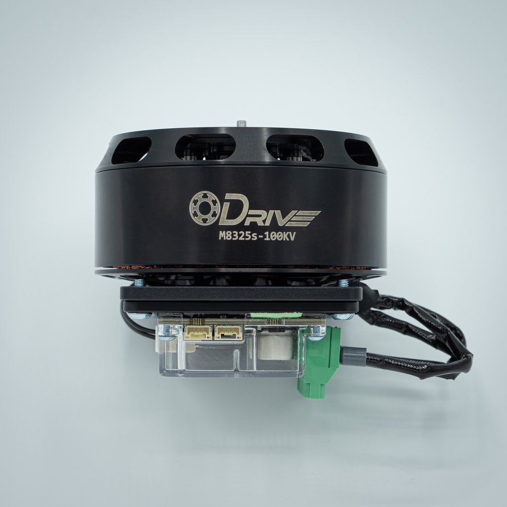
ODrive S1 mounted to a M8325S motor. The magnetic encoder is robustly protected between the two for high performance control, both fixed to a motor mounting plate.
If you need to mount your ODrive somewhere else, the ODrive OA1 contains the same magnetic encoder as the S1, Pro, and Micro, connected to a high-reliabity RS485 interface, helping bring the advantages of a magnetic encoder to any system.
Note that while all the guidelines and points raised below are true of the specific sensor we’re utilizing, much of the theory also applies to other magnetic encoders.
Basic Theory
Magnetic encoders sense, well, magnets! Specifically, they sense a rotating magnetic field, using two or more hall sensors — specialized sensors that can measure a magnetic field strength — to determine the orientation of the field.

Each hall sensor is oriented in a specific direction, and measures the strength of the magnetic field along that direction. As the magnet rotates, the strength of the field in each direction changes, and with some trigonometry (helpfully computed onboard the sensor), the absolute angle can be determined.
Design Consideration
Magnet Choice
When choosing a magnet for use, all magnetic encoders require the use of a diametrically polarized magnet. While typical (“axially polarized”) magnets have their poles oriented at the top and bottom of the magnet, diametrically polarized magnets have a field oriented perpendicular to the magnet’s cylindrical axis. This orientation ensures the magnetic field rotates along with the magnet, enabling accurate angle measurement. Otherwise, the magnetic field wouldn’t change as the magnet rotates, so there wouldn’t be anything for the sensor to measure!

We like the magnets on our store — they’re strong, high quality, and tolerant of temperatures up to 120°C. However, similar magnets in different sizes can be obtained from DigiKey, McMaster-Carr, and many other places. Ensure your magnet is high-grade neodymium — we recommend grades of N42 or above.
Tip
A suffix of -SH (such as N45SH) means the magnet can operate at a higher temperature — typically up to 120°C — as opposed to 80°C for normal magnets. This can make all the difference when bonded to a motor shaft that’ll get hot!
Magnet Mounting
It’s critical that your encoder magnet is coupled securely to the motor shaft. For proper, safe motor control, the ODrive relies on an accurate, reliable measurement of the motor’s shaft angle — incorrect measurements can lead to everything from poor control, to spinout errors, to erratic behavior and damage. Your magnet should be press-fit, clamped, or glued to a magnet holder and/or motor shaft with a strength to ensure that even rapid motor movements won’t lead to any slippage whatsoever — a loose magnet holder is a fast track to frustrating errors and poor performance.
As a general rule of thumb, you can aim for a 0.5-3mm distance between your magnet and the magnetic encoder sensor on the ODrive or OA1. While the magnets sold on the ODrive shop are strong enough to enable direct mounting to a ferromagnetic shaft or magnet holder/sleeve (with 2-3mm of stickout), not all magnets will be. If direct contact with a motor shaft produces a weak field or inconsistent sensing, a non-magnetic (e.g. aluminum, plastic, brass, etc) spacer or shim may be necessary.

The spacing between the top surface of the IC and the close face of the magnet suggested should be between 0.5 and 3.0mm in most situations.
Tip
For more information on magnet spacing with an OA1 specifically, please see the appropriate Magnet Mounting section.
Materials
When designing a system that utilizes a magnetic encoder, materials selection can also come into consideration. Ferromagnetic materials (such as iron, steel, and some stainless steel alloys) will attenuate or distort the magnetic field.
It is strongly suggested that your magnet has at least 2-3mm of stickout if using a ferromagnetic magnet holder to retain full field strength.
Generally, any plastic (ABS, PLA, PETG, Nylon, etc) will not be ferromagnetic, as well as metals such as aluminum, copper, brass, and certain alloys of stainless steel (notably 304 and 316).
Tip
Use of a 3D printed design can remove the possibility of ferromagnetic interference, as thermoplastics are not generally ferromagnetic.
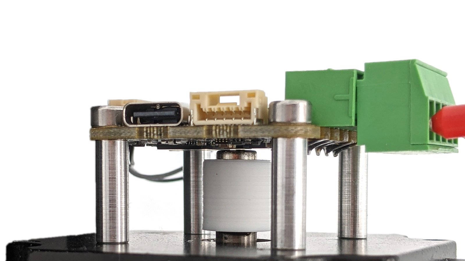
Detail photo showing magnet installation on the shaft of a motor, glued into a 3D printed magnet coupler. Note the spacing between the magnet and OA1. Click to enlarge.
Additionally, presence of ferromagnetic materials within a roughly 2mm radius of the encoder can disort the magnetic field and cause poor performance; ensure sufficient space exists in your design to minimize this risk. This 2mm radius applies to both horizontal and vertical spacing.
Alignment
Magnetic encoders rely on precise alignment between the magnet, motor shaft, and encoder IC. Typically, the total misalignment between the encoder, magnet, and shaft should be kept under +/- 0.5mm. Additionally, the magnet (and motor shaft) must be perpendicular to the surface of the encoder IC.
- Overall, make sure that:
The surface of the IC and of the magnet are parallel to one another.
The center of rotation of all three items are along the same axis.
Caution
Common pitfalls include when a user “eyeballs” the ODrive or OA1 mounting, produces a 3D printed part with loose tolerances, or has a weak/flexible mounting bracket.
Any and all of the above severely effect the encoder performance.
A common symptom of poor alignment is POLE_PAIR_CPR_MISMATCH errors, or a high amount of velocity ripple as the motor is spinning, manifesting in audible noise and vibration.
Below are two (exaggerated) examples of common errors, showing a skewed shaft/magnet (Fig. A), and a magnetic encoder IC mounted off-center to the shaft/magnet (Fig. B).

Your setup should NOT resemble either of the above depicted scenarios.
Installation
Generally, a 3D printed or simple machined coupler with the help of superglue, epoxy, or red Loctite can be used in many scenarios for an easy mounting solution. Press-fit couplers are economical at scale, but require proper tolerancing and machining for a robust interferance fit. Careful that an apparently secure friction fit does not accidentally cause magnet slippage over time. When in doubt, add some glue!

Two styles of magnet coupler to keep the magnet rigidly secured and coaxial to the shaft.
Tip
In applications with tight radial space constraints, the magnet can be glued directly to the end of the motor shaft, with no surrounding coupler. However, in these situations it’s critical that a precise alignment jig is used during assembly and gluing to ensure proper magnet alignment and spacing.
Caution
Changes in ODrive mounting or magnet rotation relative to the motor shaft will invalidate any encoder calibration results produced prior.
Harmonic Compensation
Of course, the real world isn’t perfect, and tolerance stackups can quickly exceed the +/- 0.5mm recommended magnet mounting error. The ODrive has an experimental harmonic compensation. feature that automatically measures and corrects for magnet mounting error and misalignment. Use harmonic compensation if experiencing minor but persistent misalignment-induced velocity ripple, or if magnet mounting precision demands exceed your standard alignment capabilities.
While not a substitue for best practices and careful design, harmonic compensation can correct for small misalignments and errors in encoder mounting, helping fully optimize any system’s performance.
Validation
S1/Pro/Micro
To ensure your magnet can be correctly sensed with the Pro/S1/Micro, you can call <odrv>.onboard_encoder0.get_field_strength() in ODrivetool or the Web GUI . A value above 0.045 is a sign it’s usable, lower field strengths will result in greater noise and error.
By default, the ODrive does not require that the field strength is in limits to run. The requirement is configurable through <odrv>.onboard_encoder0.field_check_mode with the following options:
OA1
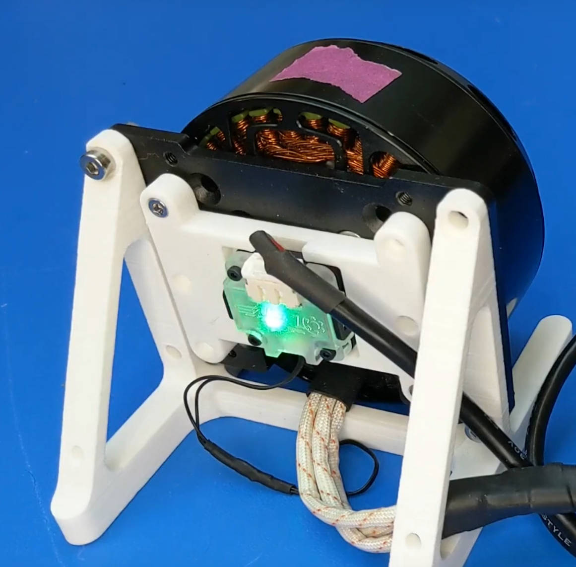
The OA1 has an indicator LED reflecting field strength. Green is good, otherwise the magnet cannot be successfully read, either being too near or too far away.
For more information specific to the OA1, please refer to the OA1 Datasheet.
Mounting Examples and Pitfalls
Using magnets that are too weak and/or too close to a ferromagnetic body (such as the motor shaft or a ferromagnetic coupler/sleeve) may result in distortion or attenuation of the fields. Below depicted are some common setups and errors.

The simplest mounting method is with a strong magnet (such as that from our shop), connected to the motor shaft via a 3D printed (non-magnetic) coupler, or directly with some glue. This ensures minimal field distortion, and good alignment (assuming the magnet is centered precisely if gluing).

If you’re using a strong magnet with a ferromagnetic coupler, ensure an adequate stickout of 2-3mm to avoid the coupler distorting or attenuating the magnet’s fields.

If using a weaker or smaller/thinner magnet, it’s important to ensure adequate spacing from ferromagnetic materials, such as the motor shaft. Mounting the magnet flush will attenuate the fields, so a plastic spacer of 1-2mm can be added between the magnet and the shaft to ensure adequate field strength.

A convenient solution can be to mount an encoder magnet in a machined bore in the motor shaft. However, as with using ferromagnetic couplers, this requires a stronger magnet, and you should ensure 2-3mm of stickout to avoid distorting the fields.
Resources
To help find optimal magnetic encoder mounting for non-standard magnets, use Monolithic Power’s “Magnetic Simulation Tool”. The magnetic angle sensor used on the ODrive S1, Micro, Pro, and OA1 is the MA702.