Hardware Configuration
Power System
Trip Levels
To prevent damage to the power supply, you must configure the ODrive such that it never pulls too much power out of the power supply, or puts too much power back into the power supply.
For this, the ODrive continuously measures the supply voltage and estimates the current going in and out of the power supply (referred to as DC voltage and DC current). When DC voltage or DC current exceeds the user-configured limits, the ODrive turns off the motor to prevent damage to the power supply (and/or itself).
DC voltage Limits:
In almost all cases, you should at least configure the overvoltage trip level.
In general it is also advisable to set the undervoltage trip level, although most AC/DC supplies will simply shut down and not take permanent damage if the ODrive pulls too much power.
Both voltage limits should be set to the rated voltage of your power supply, with a bit of a margin in both directions. This margin accounts for the voltage drop between the power supply and the ODrive. For most systems, a margin of ±2V is a good starting point, but may need to be larger if your DC cables are long or thin.
Note
These limits cannot be set beyond the ODrive’s own rated limits.
DC current limits:
These limits are typically only needed for batteries.
Set them according to the discharge and charge rating of your battery. The ODrive’s DC current estimate can be quite noisy, so you will need to add a bit of a margin.
Active Power Limit
⇒ New in Firmware 0.6.9
Note
This feature is experimental. It has been tested on some setups, but we’re looking for more validation on more user setups. Please let us know how it works for your setup!
In addition to Trip Levels, the ODrive also supports active DC power limiting. This means the ODrive can actively reduce the motor torque to stay within a specified DC power range.
In other words, at low speeds the motor’s torque capabilities can be optimally used whereas at high speeds the power supply’s power capabilities can be optimally used.
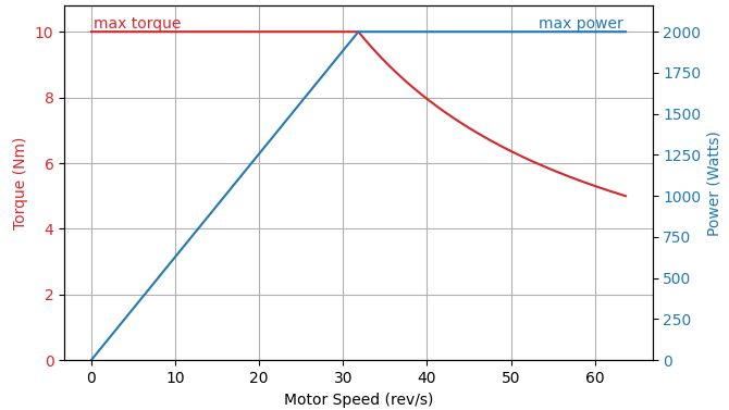
Torque and Power vs Speed.
The permissible range can be expressed in terms of DC power (in Watts) and/or DC current (in Amps), using the properties below (click for details).
DC current range:
<axis>.config.I_bus_soft_min…<axis>.config.I_bus_soft_maxDC power range:
<axis>.config.P_bus_soft_min…<axis>.config.P_bus_soft_max
The lower bounds must be negative and the upper bounds must be positive. Both ranges default to -INFINITIY … INFINITY, which effectively disables them.
If a brake resistor is used (ODrive S1 only), the limits are applied before taking into account the brake resistor.
This means that I_bus_soft_min should be set to -(max_power_supply_regen_current + max_brake_resistor_current)
(or accordingly for P_bus_soft_min).
Regenerated Power
When operating at speeds exceeding those commanded by the controller, or during braking, the ODrive functions as an electrical generator,
feeding current back to the power supply.
The maximum regenerated current is set by dc_max_negative_current.
If this limit is surpassed, the ODrive will trigger a DC_BUS_OVER_REGEN_CURRENT fault.
It is important to set this value in accordance with the allowable negative current of your power source.
Some AC/DC supplies have sensitive overvoltage protection, and any amount of regenerated power will cause the supply to shut down. To avoid this, a high power diode can be installed between the power supply and ODrive. The diode should be rated for above the operating voltage of the ODrive, and for the maximum continuous current that will be drawn from the power supply.
A suggested diode for this application is the SMC SK2S120-100. It is a dual diode array, however only one of the internal diodes needs to be used.
Note
It is strongly suggested that a diode on the power supply should only be used with ODrives that have a brake resistor control feature, with a properly connected brake resistor and proper software configuration.
Additionally, Voltage Feedback (S1 Only) should be enabled when using a power supply diode.
Using an external regen clamp removes the requirement for a power supply diode.
Brake Resistors (S1 Only)
Important
For ODrives without brake resistor control, an external Regen Clamp can be used.
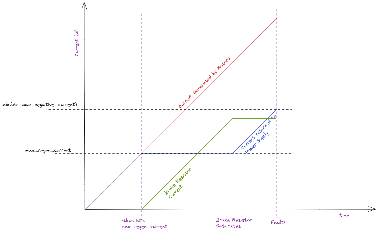
The brake resistor control feature can dissipate surplus regenerated energy through an external brake resistor.
If enabled, energy dissipation begins once the regenerated current reaches max_regen_current,
and continues until the regenerated power drops below this limit or until the resistor is fully saturated.
To enable the brake resistor control feature:
set the
<odrv>.config.brake_resistor0.resistancevalue according to the resistorset
<odrv>.config.brake_resistor0.enableto True
Voltage Feedback (S1 Only)
ODrives equipped with a brake resistor control feature can guard against the DC bus voltage rising.
This feature requires the brake resistor to be active, and enable_dc_bus_voltage_feedback must be True.
If the detected DC bus voltage goes above the provided limit, surplus power is diverted to the brake resistor:
ODrive.vbus_voltage ==
dc_bus_voltage_feedback_ramp_start, => brake_duty_cycle += 0%ODrive.vbus_voltage ==
dc_bus_voltage_feedback_ramp_end, => brake_duty_cycle += 100%
Suggested settings:
dc_bus_voltage_feedback_ramp_start= nominal bus voltage + 2Vdc_bus_voltage_feedback_ramp_end= nominal bus voltage + 6V
Note
This feature is active even when all motors are disarmed.
Warning
Setting dc_bus_voltage_feedback_ramp_start below the nominal bus voltage will quickly saturate the brake resistor.
The brake resistor will not be able to dissipated any regen current, and can produce unintentional and potentially dangerous amounts of heat.
Temperature Regulation
Thermistors
Over Temperature Current Limiting
The ODrive monitors the temperature of the inverter (the onboard power electronics) and optionally the motor and automatically reduces motor current when either of them approaches a predefined limit.
Both thermal zones are handled independently. For each enabled thermal zone,
the ODrive starts limiting the motor current when the temperature exceeds temp_limit_lower.
The current limit will then ramp down, ending with 0A once temp_limit_upper is reached.
If the temperature continues to rise past temp_limit_upper + 5°C, the ODrive will exit CLOSED_LOOP_CONTROL with an error of either INVERTER_OVER_TEMP or MOTOR_OVER_TEMP, depending on which thermal zone exceeded this threshold.
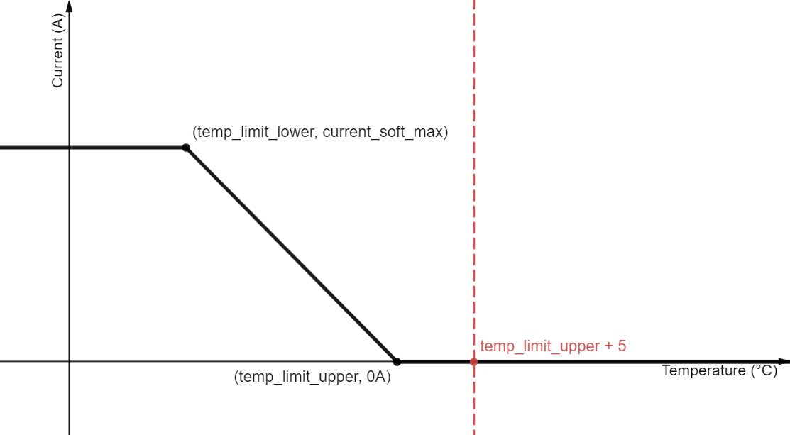
Current Limit vs. Thermistor Temperature
The variables related to thermal current limiting can be found here:
Motor:
Temperature estimate:
<axis>.motor.motor_thermistor.temperatureThermistor configuration: see below
Current limit ramp configuration:
Inverter:
Temperature estimate:
<axis>.motor.fet_thermistor.temperatureCurrent limit ramp configuration (read-only):
The inverter’s current limit ramp is always active while the motor ramp can be enabled by setting
motor_thermistor.config.enabled to True.
Motor Thermistor Configuration
The motor thermistor can be connected either directly to the ODrive or to an OA1 encoder that is connected to the ODrive.
Direct Connection: Connect the thermistor wires to THERMISTOR+ and THERMISTOR- (Pro, S1, Micro) (polarity does not matter).
Single Wire Thermistor
Some motors only have one thermistor lead while the other pole is shared with the hall effect sensor’s ground. In this case you leave the ODrive’s THERMISTOR- floating, assuming that the hall effect sensors are connected to the ODrive.
Indirect Connection via OA1: Connect the thermistor to the OA1’s dedicated thermistor connector. Set
motor_thermistor.config.gpio_pinto 256.Set the thermistor parameters:
motor_thermistor.config.r_ref: Resistance of the thermistor at the reference temperature (usually at 25°C). This can be found in the datasheet of your thermistor and is usually denoted as R_25.motor_thermistor.config.beta: Beta value of the thermistor. Can be found in the datasheet of your thermistor. Sometimes denoted as B (25/85) or similar.motor_thermistor.config.t_ref: Reference temperature (in °C) for whichr_refis given. Defaults to 25.
⇒ New in Firmware 0.6.11
motor_thermistor.config.mode=ThermistorMode.PT1000⇒ New in Firmware 0.6.11, Experimental
motor_thermistor.config.mode=ThermistorMode.KTY83_122⇒ New in Firmware 0.6.11, Experimental
motor_thermistor.config.mode=ThermistorMode.KTY84Set both
motor_thermistor.config.temp_limit_lowerandmotor_thermistor.config.temp_limit_upperaccording to your motors datasheet.Set
motor_thermistor.config.enabledtoTrue.
Warning
Thermistor resistances exceeding 200kΩ (e.g. a 100kΩ thermistor in cold weather) may result in a spurious THERMISTOR_DISCONNECTED error.
This can be mitigated by setting motor_thermistor.config.ignore_disconnected to True, however this will remove the ODrive’s ability to detect defective or accidentally disconnected thermistors.
Note that temperature readings are not guaranteed to be accurate or reliable when sensing thermistor resistances exceeding 200kΩ.
Note
For users migrating from ODrive v3.*, no external circuitry is required to use a motor thermistor. All new ODrive products (Pro/S1/Micro/etc) have a built in 1k ohm voltage divider.
Fans (ODrive Pro Only)
The ODrive Pro has one 12V supply with a switched negative lead (Fan- (pinout)) on J12. This is designed to power an offboard fan which can be controlled by either of the two modules:
<odrv>.config.odrv_fanUsed for cooling the ODrive FETs. Feedback is received from the integrated
fet_thermistor<odrv>.config.motor_fanUsed for cooling the motor. Feedback is received from an offboard
motor_thermistor
Both <fan> modules use hysteresis control, where the fan is engaged once the temperature reading reaches <fan>.upper and remains on until the temperature drops below <fan>.lower,
either module can be enabled by setting <fan>.enabled to True.
Note
If both modules are activated at the same time, the hysteresis control runs for each module separately and the fan is switched on when either of the two modules requests it to be on.
Encoders
Overview
The general approach for setting up an encoder is as follows:
Select an encoder. Refer to Known and Supported Encoders to make sure your hardware is compatible.
Mount the encoder to your motor and connect the encoder signals to the ODrive. Refer to the relevant section below for instructions specific to your encoder type. Information about the ODrive’s GPIO can be found on the datasheet (Pro, S1, Micro).
Configure the ODrive:
Set
<axis>.config.load_encoderand<axis>.config.commutation_encoderto the appropriateEncoderId.Additional configuration may be necessary. Please refer to the relevant section below.
Run encoder calibration. The calibration procedure may vary depending on the type of encoder. Please refer to the relevant section below.
Important
During calibration the rotor must be allowed to rotate without any biased load. That means inertia and weak friction loads are fine, but gravity or spring loads are not okay. Heavier loads are not advised, it is recommended that you lift any wheeled robot off the ground.
The current limit during encoder calibration is set with
<axis>.config.calibration_lockin.current. The default value is enough for most applications, but can be increased for larger motors or loads.Check if the calibration was successful:
After the calibration procedure has completed, verify that
procedure_resultis equal toProcedureResult.SUCCESS. This can be done easily fromodrivetoolby runningdump_errors(odrv), or from the GUI by inspecting the ODrive icon in the bottom left corner. If instead, you seeProcedureResult.BUSYthen the calibration has not yet completed, check again after a couple more seconds.Save the settings in the ODrive for correct bootup behavior by running
<odrv>.save_configuration().
Onboard Encoder
ODrive Pro and ODrive S1 both come with an integrated magnetic encoder. To use this encoder, a diametric neodymium magnet must be mounted to the end of the motor shaft. For general purpose use we recommend the 6x5 N45SH magnets sold in our shop If this isn’t suitable, any diametric neodymium magnet with a diameter ≥ 4 mm and thickness ≥ 2.5 mm will work.
When mounting, a 1 mm gap between the onboard encoder and the magnet is ideal.
All parameters pertaining to the onboard encoder can be found at
<odrv>.onboard_encoder0.Both
<axis>.config.load_encoderand<axis>.config.commutation_encodershould be set toEncoderId.ONBOARD_ENCODER0.Calibrate by running
Incremental Encoders
Incremental encoders have two signal connections A, B, an optional index signal Z, and will require power and ground from the ODrive.
All parameters pertaining to an incremental encoder can be found at
<odrv>.inc_encoder0.Proper configuration requires the Count Per Revolution (CPR), this should be found in the encoder datasheet.
<odrv>.inc_encoder0.config.cpr= <CPR><odrv>.inc_encoder0.config.enabled= TrueBoth
<axis>.config.load_encoderand<axis>.config.commutation_encodershould be set toEncoderId.INC_ENCODER0.Calibrate by running
Note
If the index (Z) signal is not used, ENCODER_OFFSET_CALIBRATION must be run after every reboot before CLOSED_LOOP_CONTROL can be used.
If you would like to automate this process at startup, set <axis>.config.startup_encoder_offset_calibration to True.
Index Search
Some incremental encoders have an index signal (“Z”), which is triggered once per revolution at a specific position. Index search is the process of turning the axis until the index signal is encountered. In most cases, active index search is used (the ODrive spins the motor), however passive search is also possible (see further down).
If the encoder is used for commutation, index search after startup can be used to resync to a previous encoder calibration. This is preferable to re-running ENCODER_OFFSET_CALIBRATION on every startup because it will accurately restore the same calibration every time and is not affected by unbalanced load.
If the encoder is used for absolute load positioning, index search is used to restore the absolute position reference frame.
The general process is:
If the encoder is used as a commutation encoder, set up the
commutation_mapperas described below. If the encoder is used as a load encoder, set up thepos_vel_mapperas described in Index-based Reference Frame.Identify the index signal pin number N on the ODrive. For Pro this is 7 (G07), and for S1 this is 10 (G10). Set the GPIO mode:
<odrv>.config.gpio<N>_mode = GpioMode.DIGITAL
Save the configuration:
<odrv>.save_configuration().Run
<axis>.requested_state=ENCODER_INDEX_SEARCH.This will make the motor turn in one direction until it finds the encoder index.
To do this automatically after every reboot, set
<axis>.config.startup_encoder_index_searchtoTrue.
Important
ENCODER_INDEX_SEARCH should stop at the same position every time.
You can test this a couple of times by turning the motor by hand and then running ENCODER_INDEX_SEARCH again. If the motor does not stop at the same position every time, it is likely that the index signal is not working properly (see below).
Experiencing problems?
Noise on the index signal (Z) can have unexpected consequences. Watch out for these common warning signs:
When performing
ENCODER_INDEX_SEARCH, the motor does not return to the same position each time.Difficulty requesting
ENCODER_OFFSET_CALIBRATIONafterENCODER_INDEX_SEARCH, where your calibration sequence may not complete.Strange behavior after performing
<odrv>.save_configuration()and<odrv>.reboot().
One easy step that might fix this is to attach a 22nF-47nF capacitor between the ENC1_Z pin and GND.
Reversing Index Search
Ensure that the following two values are negative:
Passive Index Search
You can tell the ODrive to look for index pulses even without explicitly running an active ENCODER_INDEX_SEARCH:
<axis>.commutation_mapper.config.passive_index_search = True
In this mode, you can spin the motor manually after startup, and the ODrive will register an index event once it is encountered.
Index Search for Commutation
Configure the
commutation_mapper:<axis>.commutation_mapper.config.index_gpio= <N><axis>.commutation_mapper.config.use_index_gpio= TrueFollow the general steps in Index Search.
After the index was found, run
<axis>.requested_state=AxisState.ENCODER_OFFSET_CALIBRATION. For this step, it is recommended that you mechanically disengage the motor from anything other than the encoder so that it can spin freely.Save the configuration:
<odrv>.save_configuration().On subsequent reboots, you only have to run
<axis>.requested_state=AxisState.ENCODER_INDEX_SEARCHto restore the commutation calibration beforeCLOSED_LOOP_CONTROLcan be used.
RS-485 Encoders
RS-485 encoder signals use a differential pair A, B and will require power and ground from the ODrive.
Encoder
ODrive
Vcc
5V
A
RS485_A
B
RS485_B
GND
GND
All parameters pertaining to an RS485 encoder can be found at
<odrv>.rs485_encoder_group0.To configure, set
...config.modeto your protocol of choice:Encoder
Encoder Mode
None/Disabled
AMT212B-V
AMT212B-V-OD
TBD
ODrive OA1 Encoder
Both
<axis>.config.load_encoderand<axis>.config.commutation_encoder(unless using a different encoder for commutation or load) should be set toEncoderId.RS485_ENCODER0.Calibrate by running
Dual RS-485 Encoders (experimental)
A second RS-485 encoder can be configured using <odrv>.rs485_encoder_group1 and EncoderId.RS485_ENCODER1.
There are limitations which encoders can coexist with each other on the same RS-485 line:
AMT212B-V-OD can not coexist with any other RS-485 encoder.
AMT212B-V (not -OD) can coexist with another AMT212B-V.
With a modification, ODrive OA1 can coexist with AMT212B-V (not -OD). Contact us if this is needed.
For other combinations please get in touch with us.
Known Issue
On the ODrive S1, there is a compatibility issue when enabling both an RS-485 encoder and the onboard encoder simultaneously.
This applies to all RS-485 encoders except AMT212B-V-OD.
To work around this issue, use
<odrv>.rs485_encoder_group1/EncoderId.RS485_ENCODER1
instead of <odrv>.rs485_encoder_group0/EncoderId.RS485_ENCODER0.
ODrive Pro is not affected.
Hall Effect Encoders
Hall effect encoders have three signal connections A, B, and C, and will require power and ground from the ODrive.
All parameters pertaining to a hall effect encoder can be found at
<odrv>.hall_encoder0.The hall feedback has 6 states for every pole pair (PP) in the motor, therefore the resolution is equal to 6 * PP. Since this is lower than most incremental or absolute encoders, we need to reduce the
encoder_bandwidthto get smoother velocity estimates.Both
<axis>.config.load_encoderand<axis>.config.commutation_encodershould be set toEncoderId.HALL_ENCODER0.Calibration requires two steps, first
ENCODER_HALL_POLARITY_CALIBRATIONthenENCODER_OFFSET_CALIBRATION. This will automatically determine the order and polarity of the hall signals.
Important
Due to the relatively low resolution of hall effect encoders, ODrive Robotics recommends a different encoder type for position control or applications requiring high performance at low speeds.
SPI Encoders
SPI encoders usually measure an absolute angle, which means you don’t need to repeat the encoder calibration after every ODrive reboot.
Some of these chips come with evaluation boards that can simplify mounting the chips to your motor. For our purposes if you are using an evaluation board you should select the settings for 3.3v.
Note
The AMT23x family has a hardware bug that causes them to not properly tristate the MISO line. To use them with ODrive, there are two workarounds. One is to sequence power to the encoder a second or two after the ODrive receives power. This allows 1 encoder to be used without issue. Another solution is to add a tristate buffer, such as the 74AHC1G125SE, on the MISO line between the ODrive and each AMT23x encoder. Tie the enable pin on the buffer to the CS line for the respective encoder. This allows for more than one AMT23x encoder, or one AMT23x and another SPI encoder, to be used at the same time.
The SPI interface has three required and one optional signal connections: clock (SCK), data (MISO), chip select (nCS), and optionally data out (MOSI). Additionally, the encoder will require power and ground from the ODrive.
Encoder
ODrive
Vcc
3.3V
SCK
SPI_SCK
MISO/DATA
SPI_MISO
MOSI (optional)
SPI_MOSI
nCS
SPI_nCS
GND
GND
Note
If you want to save a wire with AMS encoders, you can also connect the encoder’s MOSI to the encoder’s Vcc instead.
All parameters pertaining to an SPI encoder can be found at
<odrv>.spi_encoder0.set
<odrv>.spi_encoder0.config.modeto the correctSpiEncoderModefor the encoder.
Important
Only the following modes are supported at this time:
CUI protocol: Compatible with the AMT23xx family (AMT232A, AMT232B, AMT233A, AMT233B).
AMS protocol: Compatible with AS5047P and AS5048A.
Identify the chip select pin number N on the ODrive, for Pro this is 17 (G17+) and for S1 this is 12 (G12).
Both
<axis>.config.load_encoderand<axis>.config.commutation_encodershould be set toEncoderId.SPI_ENCODER0.Calibrate by running
Note
If you are having calibration problems, make sure that your magnet is centered on the axis of rotation on the motor. Also make sure that your magnet height is within range of the spec sheet.
Sensorless
Warning
Sensorless mode is considered experimental in this firmware version.
The ODrive can run without encoder/hall feedback, but there is a minimum speed, usually around a few hundred RPM. In other words, sensorless mode does not support stopping or changing direction!
Sensorless mode starts by ramping up the motor speed in open loop control and then switches to closed loop control automatically.
The sensorless speed ramping parameters are in <axis>.config.sensorless_ramp.
The sensorless_ramp.vel and sensorless_ramp.accel (in [erev/s] and [erev/s^2]) parameters control the speed that the ramp tries to reach and how quickly it gets there.
When the ramp reaches sensorless_ramp.vel, <axis>.controller.input_vel is automatically set to the same velocity, in [turns/s], and the state switches to closed loop control.
If your motor comes to a stop after the ramp, try incrementally raising the sensorless_ramp.vel parameter.
The goal is to be above the minimum speed necessary for sensorless position and speed feedback to converge - this is not well-parameterized per motor.
The parameters suggested below work for the D5065 motor, with 270KV and 7 pole pairs.
If your motor grinds and skips during the ramp, lower the sensorless_ramp.accel parameter until it is tolerable.
Below are some suggested starting parameters that you can use for the ODrive D5065 motor. Motor calibration and setup must also be completed before sensorless mode will work.
<axis>.controller.config.vel_gain= 0.01<axis>.controller.config.vel_integrator_gain= 0.05<axis>.controller.config.control_mode=ControlMode.VELOCITY_CONTROL<axis>.controller.config.vel_limit= <a value greater than<axis>.config.sensorless_ramp.vel/ (2pi * <pole_pairs>)><axis>.config.motor.current_soft_max= 2 *<axis>.config.sensorless_ramp.current<axis>.config.load_encoder=EncoderId.SENSORLESS_ESTIMATOR<axis>.config.commutation_encoder=EncoderId.SENSORLESS_ESTIMATOR
To start the motor, set <axis>.requested_state to AxisState.CLOSED_LOOP_CONTROL
Gearbox Configuration
This section is about setups that have a gearbox between the motor and the load. We define N:1 as the gear ratio, meaning that the motor spins N times for every load revolution.
Note
Harmonic compensation is currently not supported when a gearbox sits between the encoder and the motor.
Single-Encoder
If you have a single encoder that sits on the motor side of the gearbox, gearbox configuration is optional. In this case, by default the pos_estimate, vel_estimate and all corresponding setpoints will be expressed in motor-shaft units.
If, instead, you want to express user-facing units on the output shaft, you can set:
<axis>.pos_vel_mapper.config.scale = 1 / NIn this case, the velocity gain units change according to Gains from “motor-torque per (motor-turns per second)” to “motor-torque per (load-turns per second)”. So if your gains were already stable before changing scale, you now need to multiply vel_gain and vel_integrator_gain by N to keep the same physical behavior.
Dual-Encoder
If you have an encoder on both the motor and load side of the gearbox, the ODrive can use the load encoder for pos/vel control while using the motor encoder for commutation.
This allows for more accurate control of the load and for absolute position control of the load.
<axis>.config.load_encoder= <load encoder><axis>.config.commutation_encoder= <motor encoder>
By default, the velocity controller uses the velocity estimate from the load encoder. If the gearbox has significant backlash or compliance, this feedback lags and resonates relative to the motor, which can make the velocity loop oscillate or go unstable. To derive velocity from the motor-side encoder instead, set:
<axis>.controller.config.use_commutation_vel= True<axis>.controller.config.commutation_vel_scale= ±1 / (pole_pairs*N)
The sign of commutation_vel_scale must be positive if the load encoder and motor encoder spin in the same direction, and negative otherwise.
Gains
If a gearbox is configured, the velocity controller gains must account for the gear ratio.
Variable |
Unit |
Scale |
|---|---|---|
\(\mathrm{\frac{Nm}{rev/s}}\) |
motor-torque per (load-turns per second) |
|
\(\mathrm{\frac{Nm/s}{rev/s}}=\mathrm{\frac{Nm}{rev}}\) |
motor-torque per load-turns |
pos_gain is not affected by the gearbox, because it is a bandwidth (unit \(\mathrm{s^{-1}}\)), which does not depend on axis scale.
Calibration Backup
You can back up calibration data and restore it later on the same ODrive or a different ODrive instead of re-running the calibration procedure.
Example use cases:
After a firmware update
Swapping out an ODrive while the motor assembly remains unchanged
End-of-line commissioning of identical robots
Below is the list of parameters you need to back up and restore for each respective calibration.
Warning
Only carry over calibration if you’re sure that it’s valid for the target assembly. See below for details what that means. Otherwise you could run into unexpected behavior, such as reduced performance, controller instability or spinout errors.
GUI button “Calibrate” /
FULL_CALIBRATION_SEQUENCEThis a combination of multiple calibrations, depending on ODrive configuration. See docs for
FULL_CALIBRATION_SEQUENCEfor details.-
<odrv>.axis0.config.motor.phase_resistance
<odrv>.axis0.config.motor.phase_resistance_valid
<odrv>.axis0.config.motor.phase_inductance
<odrv>.axis0.config.motor.phase_inductance_valid
Phase resistance as seen by the ODrive can change if you disconnect and reconnect the same motor, due to differences in contact resistance. For end-of-line commissioning, it may be more robust to use a known-good average rather than running motor calibration on each robot individually.
ENCODER_OFFSET_CALIBRATION,ENCODER_DIR_FIND<odrv>.axis0.config.motor.direction <odrv>.axis0.commutation_mapper.config.offset <odrv>.axis0.commutation_mapper.config.offset_valid <odrv>.axis0.commutation_mapper.config.scale
axis0.config.commutation_encodermust be configured before restoring these properties.offsetshould usually only be restored on the same instance of an assembly. Carrying it over to a different instance would require the rotor and encoder (or encoder magnet) to be assembled with absolute mechanical keying, as well as connecting the three motor phases to the ODrive in a consistent order.-
<odrv>.axis0.commutation_mapper.config.index_offset
<odrv>.axis0.commutation_mapper.config.index_offset_valid
<odrv>.axis0.commutation_mapper.config.scale
axis0.config.commutation_encodermust be configured before restoring these properties.The same caveats as above (for
offset) apply. ENCODER_HALL_POLARITY_CALIBRATION,ENCODER_HALL_PHASE_CALIBRATION<odrv>.hall_encoder0.config.hall_polarity <odrv>.hall_encoder0.config.hall_polarity_calibrated <odrv>.hall_encoder0.config.edge0 <odrv>.hall_encoder0.config.edge1 <odrv>.hall_encoder0.config.edge2 <odrv>.hall_encoder0.config.edge3 <odrv>.hall_encoder0.config.edge4 <odrv>.hall_encoder0.config.edge5 <odrv>.hall_encoder0.config.edges_calibrated
If your motor comes with built-in hall effect sensors and is built to sufficiently tight tolerances, it is safe to carry over the hall edge calibration to another instance of the same motor model. Verify tolerances by running calibration on a few motors. Make sure to connect the hall encoder wires and the motor phases in the same way on every instance.
Harmonic Compensation
⇒ New in Firmware 0.6.11, Experimental
If a magnetic encoder is used with a magnet that is not perfectly coaxially aligned or is slightly tilted, the angle reading gets distorted, resulting in vibration, typically at velocities ≥10rps.
For small misalignments, the distortion can be described as a 1st and 2nd harmonic with respect to the true angle. ODrive’s Harmonic Compensation allows to calibrate for this effect and cancel it out.
To start the calibration, ensure the motor is unloaded and free spinning. Run AxisState.HARMONIC_CALIBRATION.
The motor will spin for a few seconds, and the result will be available in
<axis>.config.harmonic_compensation (cosx_coef, sinx_coef, cos2x_coef, sin2x_coef).
To reset the calibration, set the coefficients to zero.
If the calibration does not yield the desired improvement in smoothness, consider
tweaking the calibration parameters in <axis>.config.harmonic_compensation
(calib_[...]).
The spin current and acceleration parameters of the calibration are taken
from <axis>.config.general_lockin.
The instructions above assume a single encoder configuration.
For dual encoder configurations (separate load and commutation encoder),
AxisState.HARMONIC_CALIBRATION and <axis>.config.harmonic_compensation
pertain to the load encoder only.
Compared to the commutation encoder, distortion on the load encoder is usually more noticeable.
If needed, the commutation encoder can be calibrated separately via AxisState.HARMONIC_CALIBRATION_COMMUTATION
and <axis>.config.harmonic_compensation_commutation.
Harmonic Compensation is recommended for all magnetic encoders and is supported for the following encoder types:
RS485 encoders (e.g. OA1)
SPI encoders (e.g. MA702)
Onboard encoder
For other encoder types, the coefficients are ignored by the estimator.
Harmonic compensation is currently not supported with a gearbox in between encoder and motor. Motor turns must correspond to encoder turns.