ODrive OA1 Datasheet

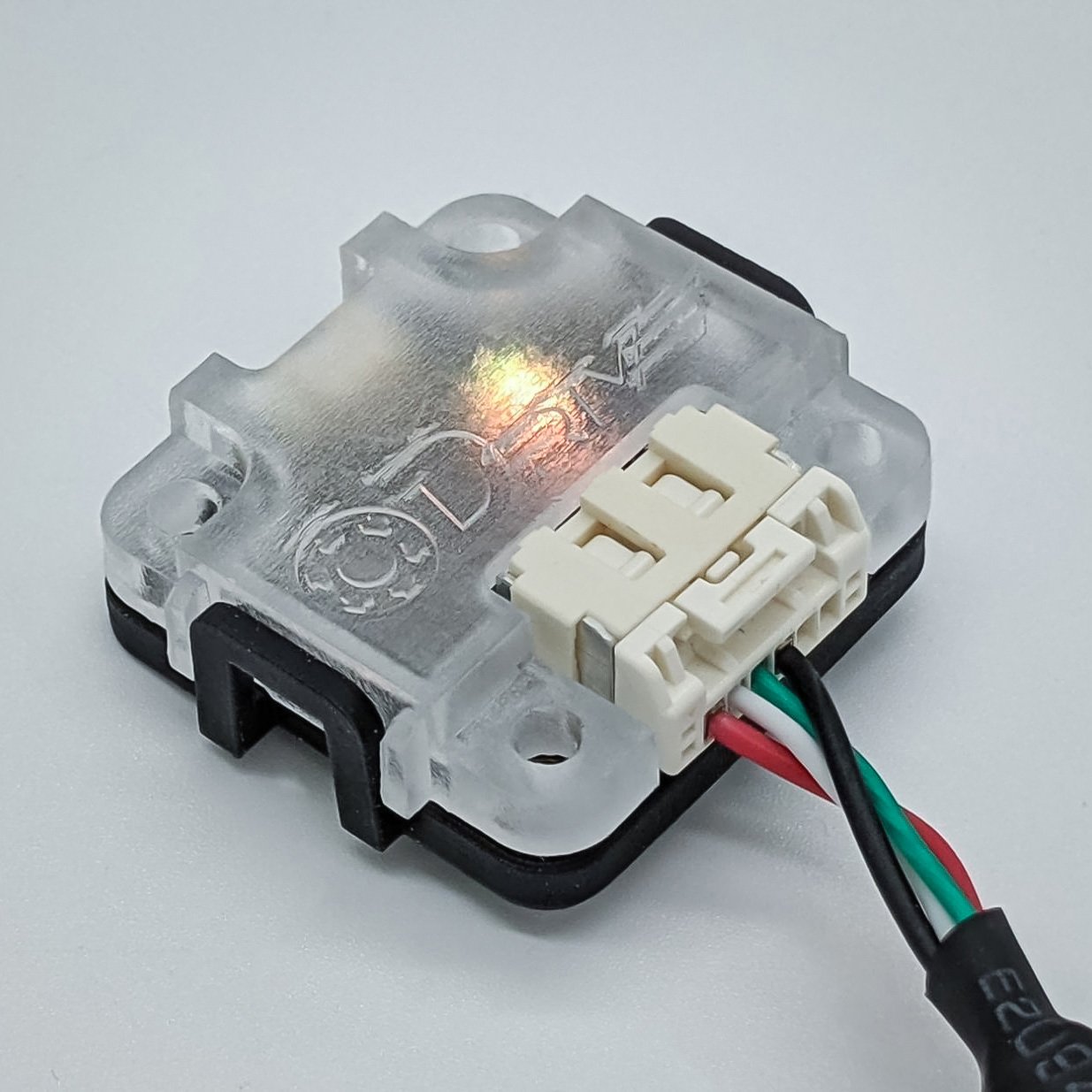
The ODrive OA1 is a compact, non-contact magnetic encoder with an RS485 interface for robust, easy connection to an ODrive Pro or S1.
It incorporates a 12-bit MA702 encoder, capable of sensing a diametrically polarized magnet’s angle at up to 60,000 RPM.
Additionally, an onboard indicator LED reports connection status and field strength, helping positioning for optimal field strength.
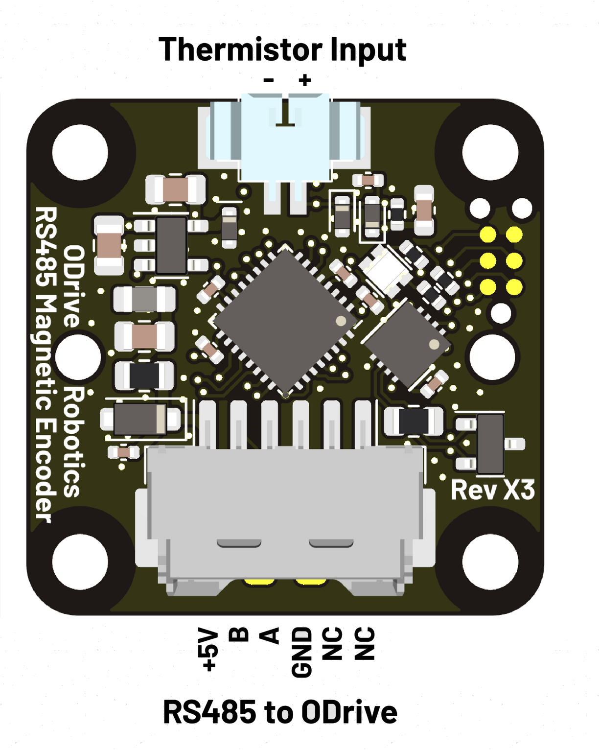
A thermistor input is provided for motor temperature sensing. Setup instructions here.
Preassembled wire harnesses to connect the OA1 to an ODrive Pro or S1 are included with the OA1 and additionally available on the shop page.
Custom encoder form factors are available - contact us.
Electromechanical Specifications
CAD
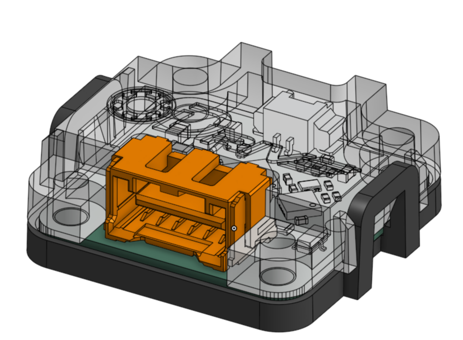
The ODrive OA1 CAD model is available on the ODrive OA1 OnShape page.

Electrical
Note
All specifications are in 0◦C ≤ TA≤ 40◦C unless otherwise noted.
Specification |
Value |
Notes |
|---|---|---|
Power Input |
4.5 – 5.5V |
Supplied from ODrive |
Signaling Protocol |
RS485 |
2Mbps |
ESD Protection |
±30 kV ±8 kV ±6 kV |
Power Lines, IEC 61000-4-2 RS485 Lines, IEC 61000-4-2 All Other Lines, IEC 61000-4-2 |
Mechanical
Specification |
Value |
Notes |
|---|---|---|
Weight |
6.3g |
With case |
Weight |
3.2g |
Without case |
Environmental
Specification |
Value |
Notes |
|---|---|---|
Humidity |
Non-Condensing |
|
Ingress Protection |
IP20 |
With case |
LED Colors
Note
On ODrive OA1s sold before Nov 10, 2023, the LED will only update when the ODrive is communicating with the OA1.
Color |
Meaning |
|---|---|
Red |
No communications from the ODrive detected. |
Blue |
Field strength too high (>112mT) |
Green |
Field strength in range |
Orange |
Field strength too low (<50mT) |
Pinout

Connectors
Connector |
Type |
Mating housing |
Mating Crimp |
|---|---|---|---|
RS485 |
Molex CLIK-Mate 6-pos |
5025780600 |
5025790000 |
Thermistor |
Molex PicoBlade 2-pos |
0510210200 |
0500798100 |
Magnet Mounting
For the OA1 to accurately sense the position of a motor shaft, a diametrically polarized magnet (such as that recommended on the shop page) must be securely attached and centered on the shaft. Off-axis applications may be supported in the future, but are not currently.
If using the magnet from the shop page, an 0.5–1mm distance from the magnet surface to the top surface of the sensor IC package is recommended. If using the OA1 PCB without a case, this corresponds to a 1.3–1.8mm spacing between the magnet and the PCB bottom. If using with a case, this corresponds to a spacing of 0.3mm above the bottom plane of the case (i.e. the magnet is partially recessed in the case hole), to 0.2mm below the bottom plane of the case.
Optimal spacing of other magnets must be experimentally determined or calculated to result in the required 50–112mT field strength.
If the magnet is positioned such that the LED color on the OA1 is consistently green, the field strength is optimal. It may be worth designing a first prototype of a OA1 sensed system with magnet position adjustment in mind.