Endstops/Homing
The ODrive can be connected to physical limit switches or other sensors that can serve as endstops. This allows for both finding a known reference position, such as homing a 3D printer or gantry system, or using an endstop to prevent damage to your mechanical system by disabling the ODrive if it travels too far in a given direction.
Before you can home your machine, you must be able to adequately control your motor in position control. It doesn’t have to be perfect, but the homing procedure relies on safe, stable closed-loop movement. See Getting Started and Tuning the Controller for more.
Endstop Configuration
Each axis supports two endstops: min_endstop and max_endstop, corresponding to negative and positive directions of travel, respectively. Note that only min_endstop can be used for homing.
For each endstop, the following properties are accessible through odrivetool or the GUI:
Name |
Description |
|---|---|
Corresponding GPIO number. |
|
Position of the endstop relative to axis zero position. |
|
Whether or not this endstop is connected/enabled. |
|
Set this to the endstop logic state upon being pressed. |
|
Filter out spurious input edges shorter than this duration. |
GPIO Configuration
If using a switch without a built-in pull-up or pull-down resistor, you need to either add an external pull-up/pull-down resistor, or set the GPIO mode to DIGITAL_PULL_UP or DIGITAL_PULL_DOWN.
Assuming your endstop is connected to GPIO X:
Configuration 1, 2:
<odrv>.config.gpioX_mode = GPIO_MODE_DIGITAL_PULL_DOWNConfiguration 3, 4:
<odrv>.config.gpioX_mode = GPIO_MODE_DIGITAL_PULL_UP
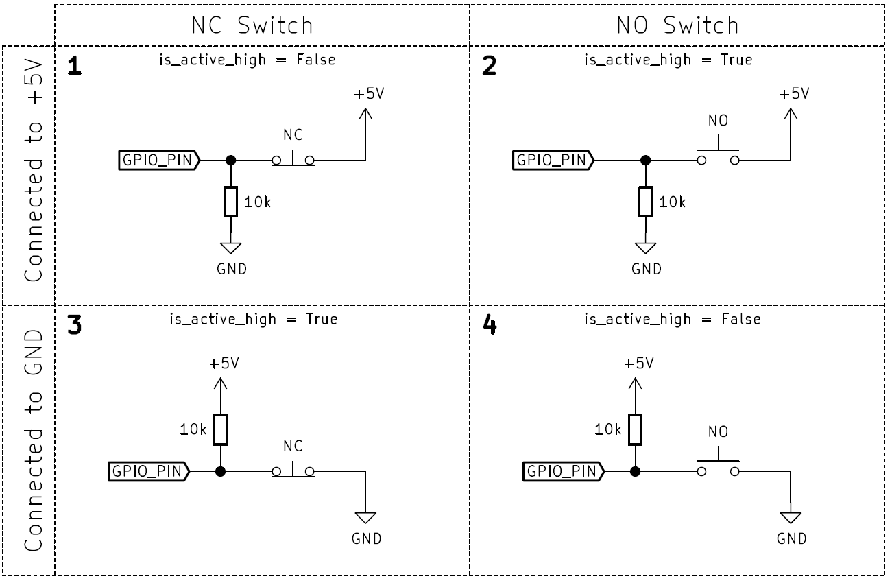
Note
Most ODrive pins have built-in pull-ups, so wiring your endstop as per configurations 3 and 4 is typically recommended, and use of DIGITAL_PULL_UP is redundant. See the “GPIO Properties” section of your ODrive’s datasheet for more information.
Warning
All pins in the ISOLATED IO domain on ODrive S1 and ODrive Pro do not support DIGITAL_PULL_UP or DIGITAL_PULL_DOWN; an external pull-up or pull-down resistor is required.
Example
Most “3D printer style” endstops have a switch connected to ground, with a pull-up resistor to +5V. If we wire such an endstop to GPIO pin G05, and want our zero position to be a quarter turn away from the endstop, we would set:
<odrv>.config.gpio5_mode = GpioMode.DIGITAL
<odrv>.axis0.min_endstop.config.gpio_num = 5
<odrv>.axis0.min_endstop.config.is_active_high = False
<odrv>.axis0.min_endstop.config.offset = -0.25
<odrv>.axis0.min_endstop.config.debounce_ms = 50
<odrv>.axis0.min_endstop.config.enabled = True
<odrv>.save_configuration() # Required for endstop changes to take effect
Validation
Once the endstops are configured you can test your endstops for correct functionality. Try manualy pressing your endstops and check the states of these variables:
<odrv>.axis0.max_endstop.state
<odrv>.axis0.min_endstop.state
A state of True means the switch is pressed. A state of False means the switch is not pressed.
Homing
Homing Sequence
The ODrive’s homing sequence works as follows:
The axis switches to Ramped Velocity Control
The axis accelerates to
homing_speedturns/sThe ODrive waits until the
min_endstopis pressedabsolute_setpointsis enabled, and the axis’spos_estimateis set to the endstop’soffsetThe axis switches to Trajectory Control
The axis moves to the new zero position.
The axis returns to
IDLE.
Starting Homing
To trigger homing, we must request the homing state:
<odrv>.axis0.requested_state = AxisState.HOMING
Note that there are a few parameters needed to be configured to ensure successful homing.
First, you must configure the homing speed and direction.
<odrv>.axis0.controller.config.homing_speedwill set the speed (in turns/s) the ODrive moves in the negative direction, towards themin_endstop. If yourmin_endstopis in the positive direction of your motor’s travel, simply set<odrv>.axis0.controller.config.homing_speednegative. Note that this will also require a positiveoffset, otherwise the zero position will be beyond the axis’s travel.The maximum acceleration during endstop search must be configured via
<odrv>.axis0.controller.config.vel_ramp_rateThe trajectory control parameters must be configured.
Homing at Startup
It is possible to configure the odrive to homing immediately after power-on.
<odrv>.axis0.config.startup_homing = True
Unless startup_closed_loop_control is also set, the ODrive will return to IDLE after homing is complete.
E-Stop
When the ODrive is in typical closed-loop control mode (other than during the homing sequence), and either the min_endstop or max_endstop are triggered, the ODrive will disarm itself with the error ESTOP_REQUESTED. This is a valuable safety measure, intended to prevent an axis from overruning mechanical limits and damaging your system.
If your system is designed to have the endstop pressed during regular motion (e.g. a hall effect sensor used for zeroing a gearbox), you can disable the endstop after completing the homing procedure.
Warning
While an endstop can be used as an emergency stop input to the ODrive, it is not SIL safety rated, and should never be used in safety-critical situations where failure would cause bodily harm or loss to human life.