PWM Input
Overview
Some GPIOs on the ODrive support PWM input with a 1-2ms pulse width, corresponding to 0% - 100% input. This is frequently referred to as “R/C PWM”, and allows to easily control the ODrive directly from a hobby RC receiver or similar device.
Refer to the datasheet (Pro, S1) of your device for a list of PWM capable GPIOs.
The PWM input can be used to control any of the numerical parameters that are otherwise writable from odrivetool or the Web GUI,
based on a user-defined linear mapping function.
Configuration
Determine the GPIO pin number N you want to use for PWM input (e.g. N=8 for G08).
Set the desired GPIO pin to PWM mode by setting
<odrv>.config.gpio(N)_modetoGpioMode.PWM. A reboot (<odrv>.save_configuration()) is required for this to take effect.Set
<odrv>.config.gpio(N)_pwm_mapping.endpointto specify which endpoint should be controlled by this PWM input. The name of this endpoint will be the property name with a leading underscore, and followed by_property. For instance, if you want to control<odrv>.axis0.controller.input_torque, the property name will be<odrv>.axis0.controller._input_torque_property.Configure how the input value (0.0 … 1.0) should map to the output value by setting
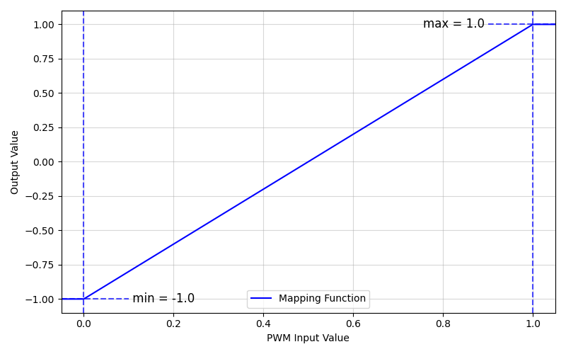
<odrv>.config.gpio(N)_pwm_mapping.minand<odrv>.config.gpio(N)_pwm_mapping.max.

Example PWM input mapping where min = -1.0 and max = 1.0
Note
The max value can be less than min, allowing you to invert the output value slope relative to the PWM input slope.
The mapping can be disabled by setting <odrv>.config.gpio(N)_pwm_mapping.endpoint to None.
Position Control Example
As an example, we’ll configure the axis to move within a range of -2 to 2 turns. This assumes your ODrive is connected to odrivetool as odrv0. In the GUI, this can be set up graphically in the configurator, so this guide is only relevant for when using odrivetool.
Make sure you’re able to control the axis0 angle by writing to
odrv0.axis0.controller.input_pos, and that the position controller is properly tuned. If you need help with this follow the getting started guide.If you want to control your ODrive with the PWM input without using anything else to activate the ODrive, you can configure the ODrive such that it automatically enters closed loop at startup. See here for more information.
Select a PWM-capable pin (see the Pro, S1 pinout pages for details).
In
odrivetool, configure the PWM input mapping, where N is the GPIO pin number selected (e.g. if pin G08 on ODrive S1 is used for PWM input,gpio(N)would be replaced withgpio8)odrv0.config.gpio(N)_mode = GpioMode.PWM odrv0.config.gpio(N)_pwm_mapping.min = -2 odrv0.config.gpio(N)_pwm_mapping.max = 2 odrv0.config.gpio(N)_pwm_mapping.endpoint = odrv0.axis0.controller._input_pos_property
Note
You can disable the input by setting
odrv0.config.gpio(N)_pwm_mapping.endpoint = NoneSave the configuration and reboot
odrv0.save_configuration()
With the ODrive powered off, connect the RC receiver ground to the corresponding GND on the ODrive, and one of the RC receiver signals to your selected PWM-capable GPIO.
Note
If using ODrive Pro or S1 and your PWM pin is in an ISOLATED IO grouping, you will need to externally power ISO_VDD/ISO_GND. See the corresponding datasheet page (Pro, S1) for more information.
You may power the receiver from the ODrive’s 5V supply if it doesn’t draw too much power, being extremely careful to avoid ground loops.
Power up the RC transmitter, and put the ODrive in closed loop control. You should now be able to control the motor’s position from one of the RC sticks.
Warning
Be sure to set up the failsafe feature on your RC Receiver so that if connection is lost between the remote and the receiver, the receiver outputs a safe value for your configured setpoint (e.g. 0 for torque/velocity, or whatever is safest for your position).
Note
If the receiver turns off (loss of power, etc.) or if the signal from the receiver to the ODrive is lost (wire comes unplugged, etc.), the ODrive will time out after 100ms and consider the input to be NAN, which in turn disarms the motor when connected to any of input_pos/input_vel/input_torque.